
Self Oscillating Amplifier for Distortion Testing

The described circuit operates as a basic inductor-capacitor (LC) filter, which is a fundamental configuration in electronic design for generating oscillations at a specific frequency. The core components include an inductor (L) and a capacitor (C) that together determine the resonant frequency of the circuit, given by the formula \( f = \frac{1}{2\pi\sqrt{LC}} \). The addition of a potentiometer (pot) allows for fine-tuning of the circuit's parameters, enabling adjustments to the oscillation stability and output characteristics.
In this particular modification, the introduction of a 100-ohm fixed resistor serves to improve the overall stability of the oscillation by providing a defined impedance path. The use of a 1k-ohm potentiometer instead of a 100-ohm pot allows for a wider range of adjustment, providing greater flexibility in tuning the circuit's response. The additional 1k-ohm resistor enhances the quality factor (Q) of the circuit, which is crucial for minimizing distortion and improving the performance of the filter. A higher Q factor indicates a sharper resonance peak, thus reducing the bandwidth of frequencies that may interfere with the desired oscillation.
The light bulb mentioned in the circuit description likely serves as an indicator of oscillation or as a load for the circuit. Its behavior can provide visual feedback regarding the circuit's operation, such as the amplitude of oscillation. The design aims to achieve low distortion, making it suitable for applications where signal integrity is critical.
Overall, this LC filter circuit is a practical example of how simple modifications can lead to improvements in performance, particularly in terms of stability and distortion reduction, making it a valuable tool in various electronic applications.The circuit is based on a simple inductor-capacitor filter circuit, and needs only a pot and a small light bulb to set and stabilise the oscillation. The frequency is fixed, and with a good inductor should be capable of very low distortion. This circuit is a slight modification of that submitted by Alfred Schaub - I added a 100 ohm fixed resistor and used a 1k pot (rather than a single 100 ohm pot), and I also added a 1k resistor to improve the circuit`s Q and reduce externally generated distortion to the lowest possible.
🔗 External reference
Related Circuits
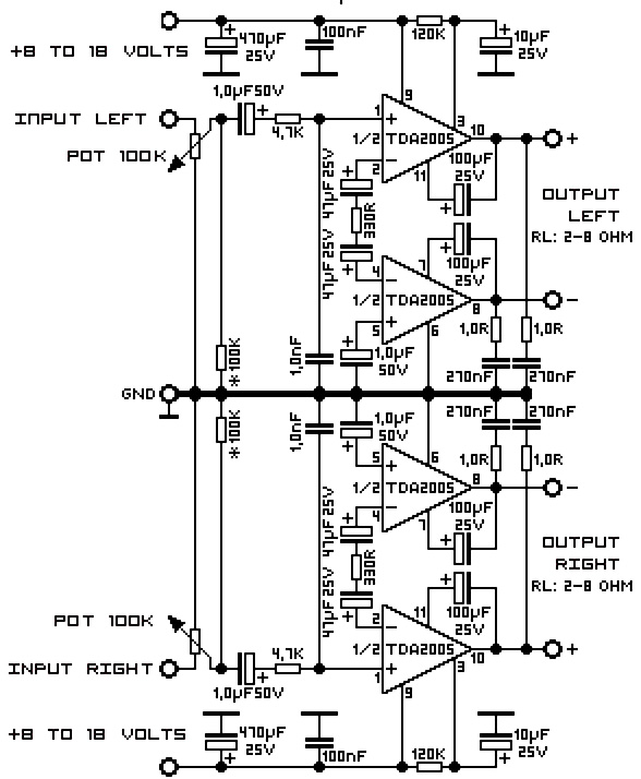
A 20W TDA2005 stereo amplifier designed for various applications, including the amplification of medium power speakers. It is suitable for automotive use; however, the power supply must be equipped with a choke of at least 150mH and should provide...
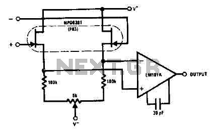
The NPD8301 exhibits excellent characteristics across its range of bias current, enhancing common mode rejection. The monolithic double NPD8301 provides an ideal low offset buffer function and features the LM10lA low drift operational amplifier. The NPD8301 is a monolithic double...
The 2N4416 JFET exhibits very low harmonic distortion, making it ideal for smooth oscillation in electronic circuits. It is particularly effective in applications where minimal harmonic content is essential for high-performance mixer circuits. Below is the circuit diagram of...
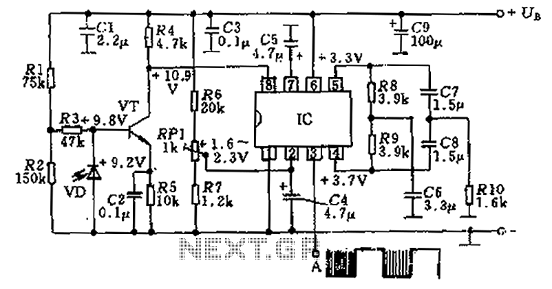
The circuit utilizes an integrated amplifier, resulting in a simple and compact design. The TDA4050 IC is employed, where a weak signal is received by the infrared photodiode (VD) and first passes through a transistor amplifier. The circuit is...
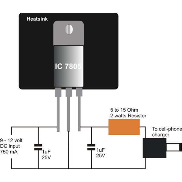
Construct a straightforward DC to DC mobile battery charger to charge your mobile phone battery at any time and location by connecting it to a 12-volt source from a car or motorbike battery. This mobile battery charger circuit is designed...
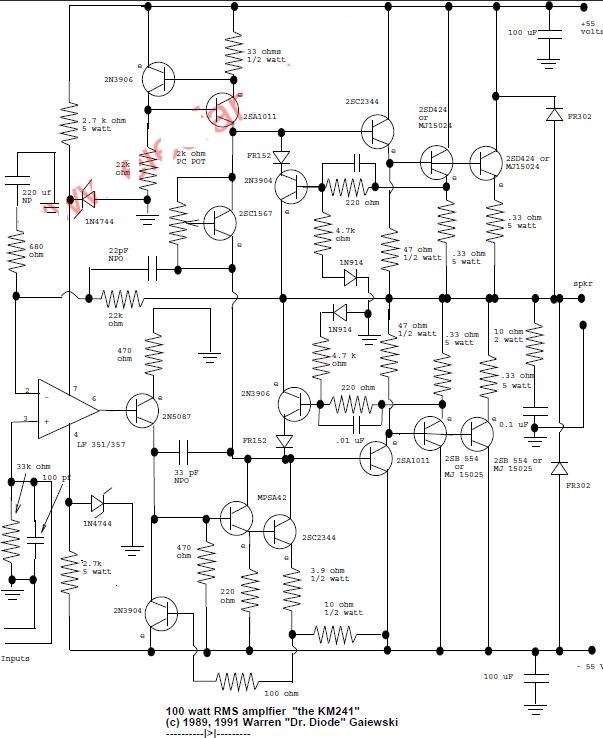
This is a 100-watt basic power amplifier designed to be relatively easy to build at a reasonable cost. It offers better performance, or musical quality, than the standard STK module amplifiers commonly found in mass-market stereo receivers. The design...