
self powered sine to square wave converter

The circuit utilizes a comparator or Schmitt trigger configuration to achieve the conversion from sine to square wave. The input sine wave signal is fed into the non-inverting input of the comparator. The comparator's reference voltage can be set at half the peak value of the sine wave to ensure accurate switching. As the sine wave oscillates, the output of the comparator toggles between high and low states, effectively generating a square wave.
To enhance the performance of the circuit, it may include additional components such as capacitors for filtering and resistors for setting the gain or adjusting the threshold levels. The output square wave can then be used to drive various digital circuits or devices requiring a clock signal.
Furthermore, the circuit's design should ensure that it maintains signal integrity and minimizes distortion during the conversion process. Proper layout considerations, such as minimizing trace lengths and using appropriate grounding techniques, are essential to prevent noise interference. The absence of an external power source also simplifies the setup, making it ideal for portable applications or testing environments where power availability may be limited.
In summary, this circuit effectively transforms a sine wave into a square wave without the need for an external power supply, making it a practical solution for various electronic applications.This circuit is intended to provide good square waves converting a sine wave picked-up from an existing generator. Its major feature consists in the fact that no power-source is needed: thus it can be simply connected between a sine wave generator and the device under test..
🔗 External reference
Related Circuits
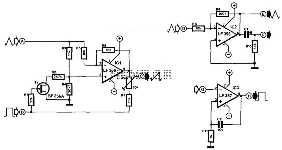
Simple function generators typically produce sinusoidal, rectangular, and triangular waveforms, but rarely generate sawtooth waveforms. The circuit depicted in Fig. 21-4(a) generates a sawtooth signal from rectangular and triangular signals. The quality of the sawtooth output is influenced by...
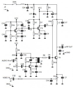
This is the circuit diagram of an audio/video modulator. The circuit converts audio and video signals into a UHF TV signal. It is designed to connect a video signal originating from a camera or other video source to a...
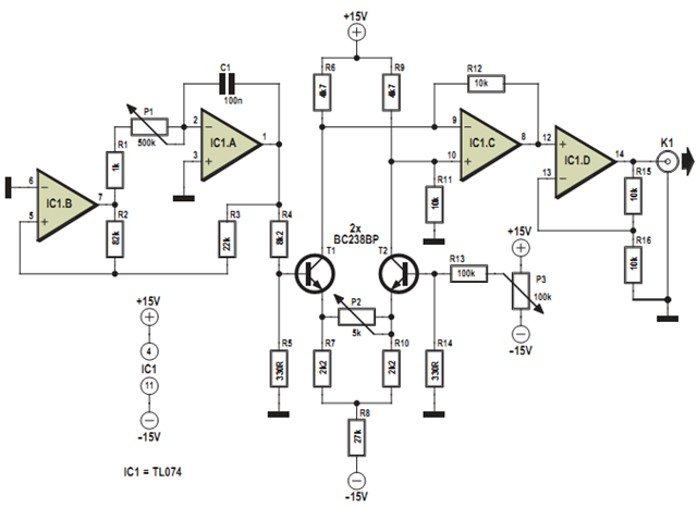
This design was developed to partially replace the well-known 8038 chip, which is no longer in production and therefore difficult to obtain. An existing design for driving a Linear Variable Differential Transformer (LVDT) sensor utilized the 8038 as a...
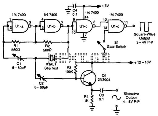
A TTL oscillator utilizing a Quad NAND Gate can operate with fundamental crystals ranging from 1 to 10 MHz. The sine wave output is derived directly from the crystal, which functions as its own filter, producing a relatively clean...
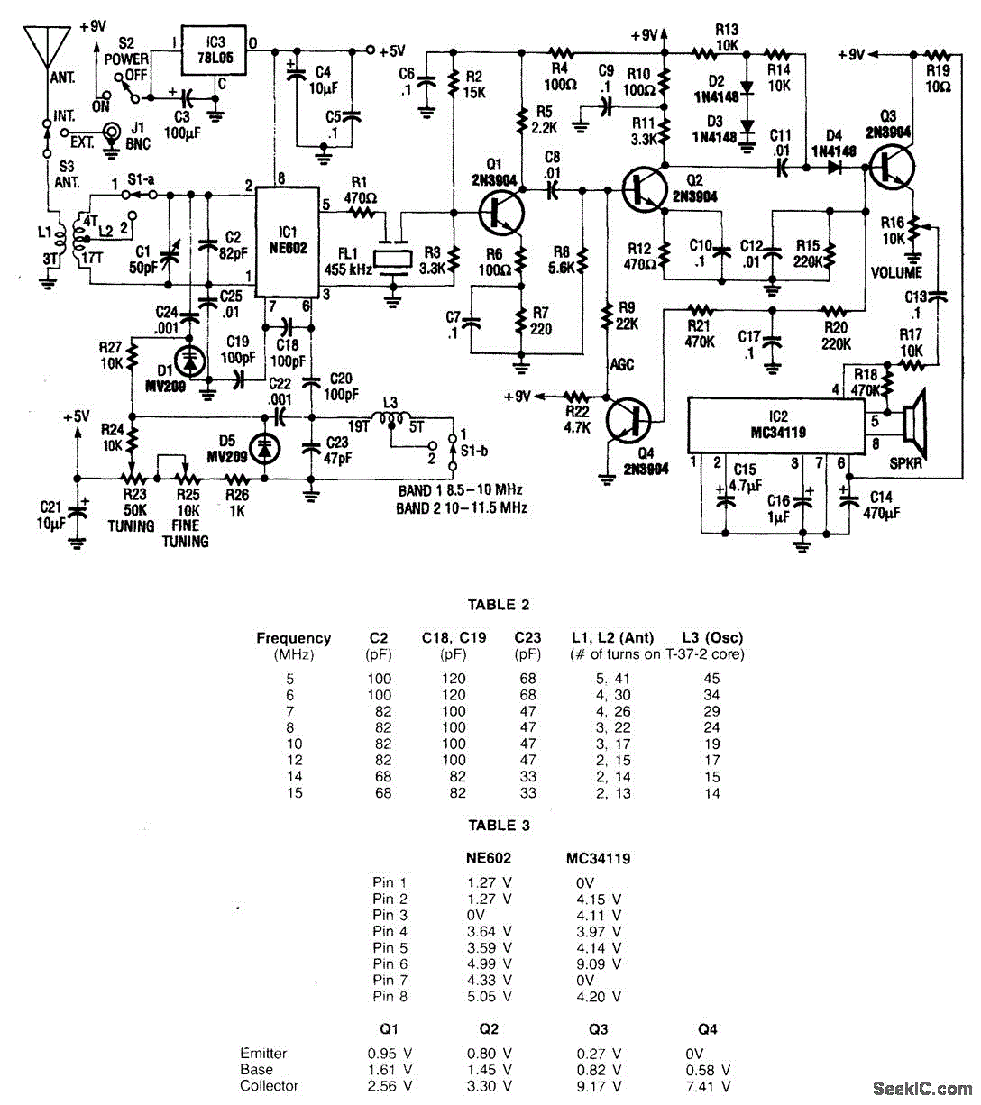
This receiver operates within the frequency range of 8.5 to 11.5 MHz across two distinct bands and exhibits a sensitivity level of less than 1 µV. The NE602 mixer is utilized to feed a 455 kHz intermediate frequency (IF)...
I keep all rights to those circuits myself. You may freely build those circuits to yourself and your friends, but commercial use of those circuits is not allowed. NOTE: Those circuits are old designs from time when I was...