
Audio/Video to UHF TV Signal Converter (Modulator) circuit diagram
")
The audio/video modulator circuit is engineered to facilitate the transmission of video and audio signals over UHF frequencies, enabling compatibility with conventional television sets. The primary function of this circuit is to take composite video signals, often provided by cameras or other video sources, and modulate them into a format suitable for UHF transmission.
The circuit typically includes several key components: a video input stage, an audio input stage, a modulator, and a power supply. The video input stage receives the composite video signal, which is then processed to ensure it meets the necessary electrical specifications for modulation. Similarly, the audio input stage handles the audio signal, preparing it for integration with the video signal.
The modulation process is crucial as it combines both audio and video signals into a single UHF signal. This is often achieved using a frequency modulation (FM) technique for the audio component and an amplitude modulation (AM) or frequency modulation for the video component. The resulting UHF signal can then be transmitted through the antenna input of a television.
The circuit design may also incorporate additional features such as signal amplification to enhance the output signal strength, filters to minimize interference, and connectors for easy integration with various audio and video sources. The availability of a complete kit, including a printed circuit board (PCB) and necessary components, simplifies the assembly process for users, allowing for straightforward construction and deployment of the modulator circuit. This makes it an accessible solution for those looking to connect non-standard video sources to traditional television systems.This is the circuit diagram of audio/video modulator. The circuit will convert an audio and video signal into a UHF TV signal. It`s desired to connect a video signal originating from a camera or other video source to a normal TV set. The audio and video signal is converted into a UHF TV signal so that the signal can be received through the TV ante
nna input. The circuit kit of this audio/video modulator available to buy at electronickits. com. You may buy the complete kit of this circuit (PCB board and the components) there. 🔗 External reference
Related Circuits
A schematic that illustrates the connections to the Clare IXDI404PI chip, which serves as both the control unit and power driver for a DIY Back-And-Forth robot. The Clare IXDI404PI chip is a dual-channel, high-speed, high-current driver designed for driving inductive...
Do you long for a beach holiday on a tropical island, but you don't have the necessary means? There is a solution: build the i-TRIXX surf simulator, put on your headphones, and escape from this mundane reality. Allow the...
The circuit is designed to operate with an audio power amplifier that uses 18V-0V-18V power rails. The specific voltage is not critical, but the feedback is referenced to an LED chain connected to a 12V rail, necessitating a separate...
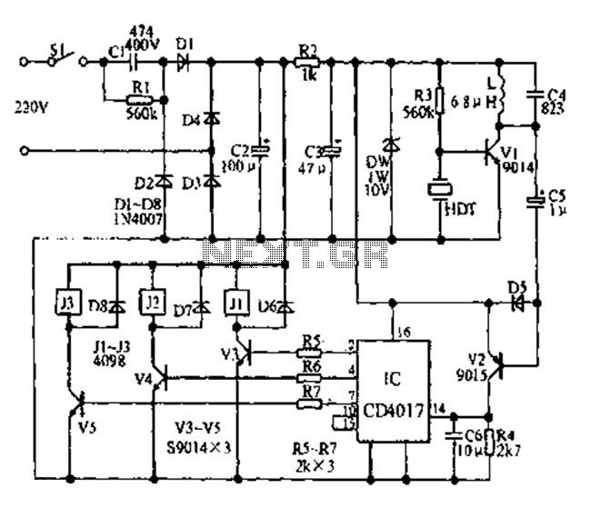
Fans can be controlled remotely with a switch that allows for speed adjustments, and this remote control can also be integrated with other household switches. Its primary feature is the use of a sub-transmission ultrasonic transmitter, which operates without...
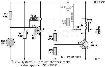
The following page outlines detail information on how to step by step design a Simple Heat Sensor Circuit. This circuit design utilized LM741 as the operational amplifier. More: Circuit Parts/Components List: Re1 = 12V relay R1 = 47K R2...
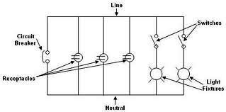
Each component of the circuit is represented in a simple block form with corresponding labels for identification, using no special symbols or language. The interconnections between these components are depicted by solid lines. The block diagrams can be read...