
Sawtooth Converter

The circuit operates as a versatile sawtooth waveform generator, leveraging the properties of triangular and rectangular signals to produce a high-quality output. The use of operational amplifiers and FETs allows for precise control over the waveform characteristics, including frequency and amplitude. The feedback mechanism involving the potentiometer ensures that the output signal can be finely tuned to meet specific application requirements.
The auxiliary circuits provide flexibility in generating the required input signals, accommodating situations where the primary input signals may not be available or suitable. The amplification stage enhances the triangular signal, ensuring that it can be effectively converted into rectangular pulses. The differentiating network plays a critical role in shaping the output, transforming the amplified triangular waveform into a rectangular format that can be further processed.
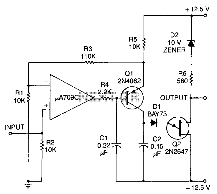
Overall, this circuit design is suitable for various applications requiring sawtooth signals, such as in signal processing, waveform generation for testing, and other electronic applications where precise waveform characteristics are essential. The specified frequency range and power supply options make it adaptable to a wide range of electronic systems. Simple function generators normally provide sinusoidal, rectangular, and triangular waveforms, but seldom a sawtooth. Th e circuit in Fig, 21-4(a) derives a sawtooth signal from a rectangular and triangular signal. Its quality depends on the linearity of the triangular signal, the slope of the edges of the rectangular signal and the phase relationship between the rectangular and triangular signals. The conversion is carried out in IC1. Whether the triangular signal at input A is converted or not by IC1 depends on the state of Tl. This FET is controlled by the rectangular signal at input B. The signal at the output of the op amp is a sawtooth (see Fig. 21-4(b)) whose trailing edge is inverted. The frequency of this signal is double that of the input signals. If in this state, the dc level of each inverted edge is raised sufficiently to make the lower level of that edge coincide with the higher level of the preceding edge, a sawtooth signal of the same frequency (but double the peak value of the input signals) is obtained.
The dc level is raised by adding input to the output of IC1 via R7 and PI. The preset should preferably be a multiturn type. Resistors R2 and R4 are 1% types. If a rectangular signal is not available, or if its peak value is too small, the auxiliary circuits (shown in Figs. 21-4(c) and 21-4(d)) will be found useful. Figure 21-4(c) amplifies the triangular input at A by 10. Differentiating network C1/R10 derives rectangular pulses from the amplified triangular signal and these are available at F.
The pulses at F are shaped by the circuit in Fig. 21-4(d) to rectangular signals that have the same peak value as the supply voltage. Capacitor C2 increases the slope of the edge; it can be omitted for low-fre-quency signals. The converter provides sawtooth signals over the frequency range of 15 Hz to 15 kHz. If the auxiliary circuits are used, capacitor CI must be compatible with the frequency of the sawtooth signal (its value lies between 2 nF and 100 pF). The supply for all circuits can be between ± 10 V and ± 15 V. Each op amp draws a current of 4 to 6 mA.
Related Circuits
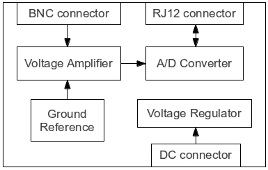
This is the preliminary draft of the pH to 1-Wire converter schematic, with some component values still pending. The original circuit operates on 12 VDC, but since the A/D converter IC requires a 5 VDC supply, the circuit needs...
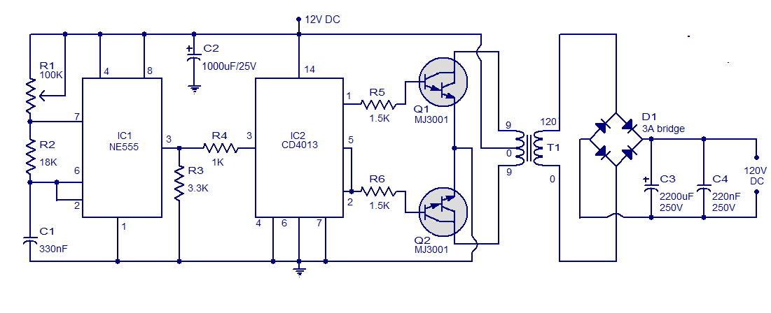
This is a simple circuit designed to convert 12V DC to 120V DC. The circuit comprises two main phases: the inverter stage and the rectifier and filter stage. The NE555 integrated circuit (IC1) is configured as an astable multivibrator,...
This circuit consists of a UJT oscillator where the timing charge capacitor C2 is linearly dependent on the input signal voltage. The charging current is determined by the voltage across resistor R5, which is precisely controlled by the amplifier....

By configuring a comparator and a transistor to control the oscillator in a charge pump circuit, it is possible to generate a regulated output of virtually any desired value. Charge pump integrated circuits (ICs) can either invert or double...
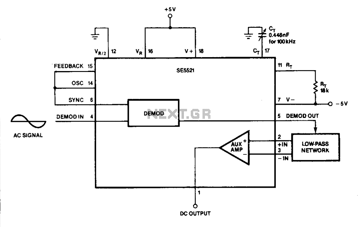
The DC output at Pin 1 varies linearly with the RMS input at Pin 4. The variable capacitor (CT) is adjusted until the sync signal is in phase with the AC signal. An AC voltmeter can be easily constructed...
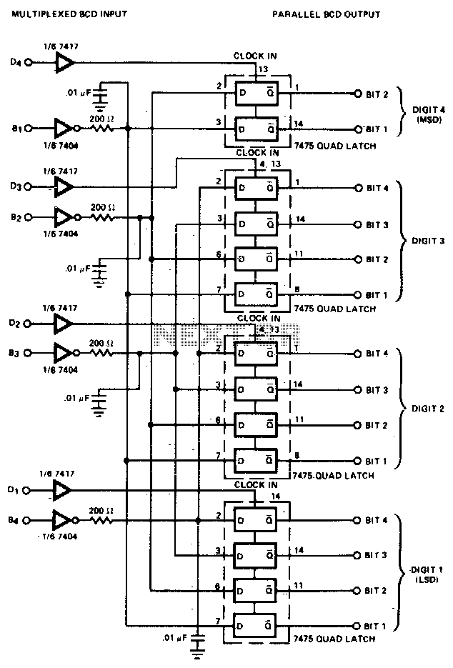
The converter is composed of four quad bistable latches that are activated in the correct sequence by the digit strobe output from the LD110. The complemented outputs (Q) of the quad latch set represent the state of the bit...