
Self runner Generator

The described circuit utilizes a rotor equipped with a tiny magnet to create precise timing for generating high voltage spikes. The rotor's movement is essential for triggering a reed switch, which subsequently activates a relay. This relay is responsible for directing energy from a recovery coil to a primary battery while simultaneously isolating the rest of the circuit from the primary battery, ensuring that the system operates efficiently.
The recovery coil plays a critical role in this configuration. It is emphasized that the coil must possess a minimum resistance of 20 Ohms, with higher resistance being preferable. This characteristic is crucial because it directly affects the voltage generated across the recovery coil as the rotor's speed increases during startup. A voltmeter can be used to monitor this voltage, which is expected to rise as the rotor accelerates.
The generation of high voltage spikes, specifically reaching up to 2000V, is contingent upon the recovery coil producing a voltage of at least 30-35V. If the coil is unable to achieve this threshold, it is recommended to enhance the coil's design by adding additional turns of wire. This adjustment increases the coil's inductance and, consequently, its ability to generate higher voltages.
The arrangement of magnets in an NSNS configuration is critical for the timing of the relay activation. The positioning of the neo magnet is designed to trigger the relay at an optimal moment—specifically, just after the north pole of the first magnet has passed the primary power coil and immediately before the next north pole approaches. This precise timing is essential for maximizing the voltage spikes produced by the circuit, ensuring that the energy transfer is both efficient and effective.
Overall, the described circuit illustrates a method of harnessing mechanical energy through careful timing and configuration of components to achieve high voltage outputs, which can be utilized in various applications requiring such voltage levels.The timing must be exact to get those high voltage spikes. I used a tiny magnet on the rotor, that triggered a reedswitch allowing the relay to pulse the energy from the recovery coil to the primary battery. In the same time the rest of the circuit is disconnected form the primary battery. The recovery coil has to have at least 20Ohms resistance, the higher the better, because when the speed rises at startup, you can see on the meter, that the voltage across the recovery coil increases.
But the 2000V spikes start to appear only when about 30-35V are reached. So if your recovery coil can not generate at least 30 volts conventionally, it will be hard for you to get those high voltage spikes. If so, just add some more turns of wire on your coil. The magnets are in NSNS configuration. You must place the neo magnet so that it triggers the relay just after the N magnet has passed by the primary power coil and just before the next N magnet.
That way you will get the high voltage. 🔗 External reference
Related Circuits
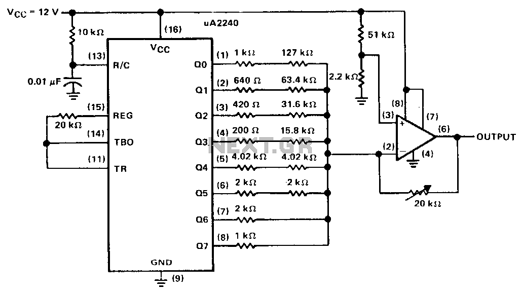
The uA2240 timer/counter, in conjunction with a precision resistor ladder network and an operational amplifier, creates a staircase generator. In astable mode, the uA2240 operates continuously after a trigger pulse is applied until it receives a reset pulse. The...
V1 and V2 are set to 5V in the simulation, but they could also be set to 10V to eliminate the need for a second power supply. Alternatively, if logic level FETs can be sourced at that higher voltage,...
This application note describes the implementation of a single-supply triangular wave oscillator using the MAX9000 integrated circuit and several passive components. The circuit employs an operational amplifier, a comparator, and a voltage reference as the main active components. The...
The hobby circuit described utilizes a unique method to generate approximately 12,000 volts with a current of about 5 microamperes. It employs two silicon-controlled rectifiers (SCRs) that form two pulse generator circuits. These SCRs discharge a 0.047 microfarad, 400-volt...
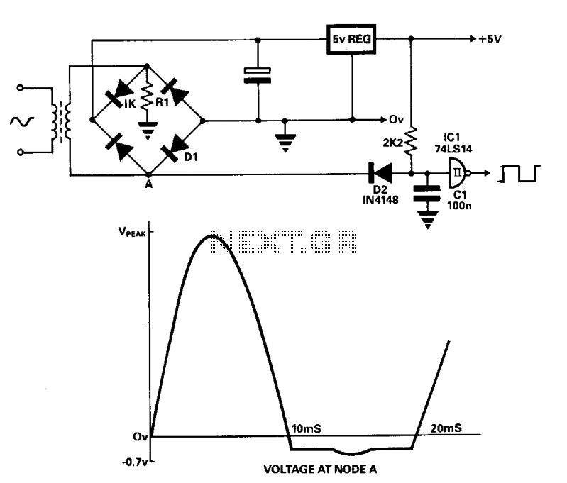
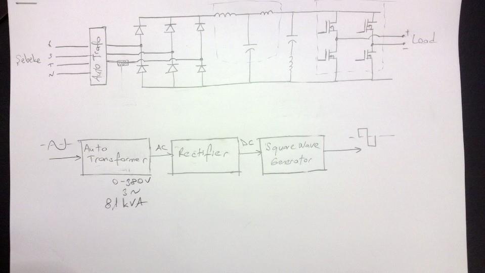
A line frequency square wave with a 1:1 duty cycle can be generated using only three components and a buffer from the power supply. During the alternate half-cycle, point A is clamped to approximately -0.7 V by diode D1...
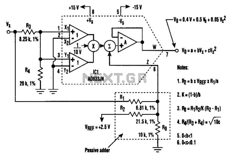
A circuit utilizing a single analog multiplier and five precision resistors can produce an output voltage (Ko) that represents a second-order polynomial. This circuit implements the quadratic function. The input terminals of IC1 are configured to create a positive...