
Sending Data Over IR Wireless Infrared Communication Link System

The circuit described utilizes a basic infrared communication setup, consisting of an infrared LED (emitter), a phototransistor (receiver), a push button switch, a red LED for visual feedback, and a power source. The infrared LED is responsible for emitting infrared light when activated by the push button. The phototransistor detects this light and changes its state accordingly, allowing or blocking current flow to the red LED.
In practice, the 9V battery serves as the power supply for the entire circuit. The infrared LED is connected in series with the push button, ensuring that it only activates when the button is pressed. The phototransistor is connected in a manner that its output state can influence the red LED. When the infrared light is emitted, the phototransistor enters a conductive state, leading to the red LED turning off. Conversely, in the absence of infrared light, the phototransistor is non-conductive, allowing the red LED to illuminate.
This circuit exemplifies the fundamental principles of infrared communication by demonstrating how binary data can be represented through light signals. The transition between the states of the red LED serves as a visual indicator of the data being transmitted. In more advanced applications, additional circuitry can be integrated to enhance data processing, error correction, and signal modulation, allowing for more complex data transmission protocols. The incorporation of a microcontroller, such as the 18F452, enables further processing of the received data, facilitating its use in various applications, including remote controls, wireless sensors, and data communication systems.The core infrared theory for getting this tutorial working was already described in the Infrared Receiver tutorial, so I`ll run through an abridged version here. First I`ll describe as an overview what infrared is and how it relates to our lives, then I`ll go further to how we can transmit digital data over this wireless link.
The way that the inf rared transmitter and receiver pair works is similar to the way that our eyes work. We can see many different colors and depending on what we see, we act. The phototransistor functions in a similar way, it reacts depending upon the intensity of infrared light being shined at it. The real difference between the two similar cases above is that our brains already have a way to interpret the different wave lengths of color, where the infrared LED and phototransistor need some intelligent electronics in order to know what to do when certain data is transmitted.
If you`re still scratching your head in confusion as to how 0`s and 1`s can be transmitted using the IR emitter and phototransistor, then build the circuit seen below and it should help make things more clear: Here`s how the circuit above works: The 9v battery is hooked up to both the IR Emitter and Phototransistor. The IR Emitter, however, is never turned on unless you press the push button. Since the emitter is not powered on, the phototransistor won`t allow current to flow through it, so current will instead flow through the red LED.
This means until you press the push button, the red LED remains on. After you press the push button, the emitter shines brightly at the phototransistor and the red LED turns off. Here`s a video of this circuit in action: This should give you a much better visual of how digital 0`s and 1`s can be transmitted wirelessly using these two infrared components.
When the red LED shines, you can see a digital 1. When we press the push button and the red LED turns off, that would be a 0. Now if we replace a steady stream of digital 1`s and 0`s where the push button is the receiving phototransistor will see the same stream of digital 0`s and 1`s. Bingo! Wireless transmission. Feed the received stream of digital data into the receiving 18F452 microcontroller and the system is complete.
🔗 External reference
Related Circuits
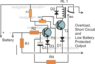
The battery voltage must pass through resistor R1 before reaching the output load. As a result, the current flowing through R1 is proportionately transformed into a voltage across it. When the battery voltage drops below a certain threshold, the...
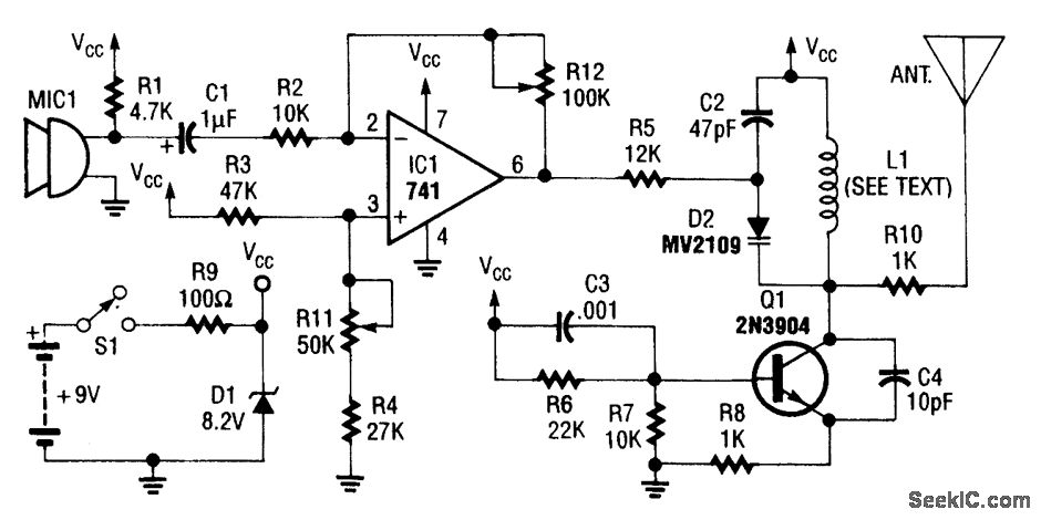
An operational amplifier integrated circuit (741) amplifies the audio signal from microphone 1 (MIC1), with resistor R12 determining its gain. The amplified audio signal is then directed to the oscillator circuit, which includes transistor Q1 and associated components. D2...

This circuit is a simple remote-controlled relay capable of switching lamps or other devices. D1 can be a phototransistor, LDR, or an infrared transistor. The circuit is controlled using an IR remote, similar to a TV remote control, when...
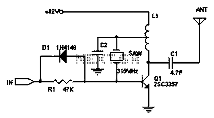
The circuit principle involves the use of an LC oscillator, which typically experiences significant frequency drift. Surface Acoustic Wave (SAW) devices have emerged as a solution to this issue, offering frequency stability comparable to that of crystal oscillators. SAW...

In forward inverter system applications, the IRZ110 is used to receive a signal when the line is shown in Figure 12-39. In this application, the next channel utilizes the IR 2110 and shares an input pulse signal that determines...

To transmit video and audio signals to multiple televisions simultaneously, a video amplifier splitter utilizing a transistor can be employed. A video amplifier splitter is an electronic device designed to distribute a single video and audio signal to multiple output...