
Darlington phototransistor type light control switch circuit diagram sensitive application

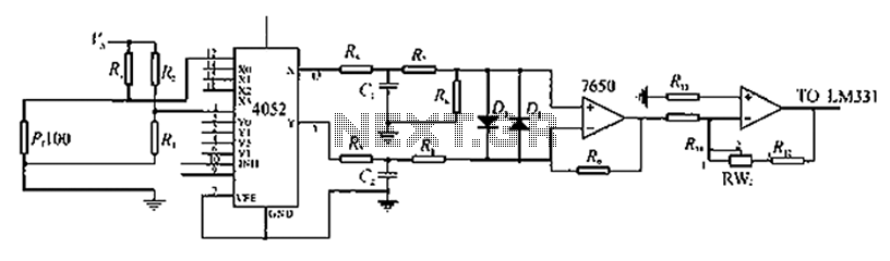
The Darlington phototransistor circuit utilizes a pair of transistors configured to amplify the current, making it highly sensitive to light. This configuration is particularly effective in applications where low levels of light need to be detected, such as in reflective light sensors. The circuit operates by allowing light to strike the phototransistor, which generates a small current proportional to the intensity of the incoming light. This current is then amplified by the Darlington pair, resulting in a significant increase in output current.
In a typical application, the circuit may include additional components such as resistors to set the biasing conditions for the phototransistor, and capacitors for noise filtering. The output can be connected to a microcontroller or a relay, enabling the control of larger loads based on the detected light levels. The design ensures that the circuit can function effectively in various lighting conditions, making it suitable for automation systems, security devices, and other light-sensitive applications.
Overall, the Darlington phototransistor circuit represents an efficient solution for detecting reflected light signals, with its high sensitivity and amplification capabilities making it ideal for a wide range of electronic applications.Darlington phototransistor type light-sensitive switch control circuit application As a result of Darlington type phototransistor do sensitive element, the low light sensitive for the detection of the reflected light signals.
Related Circuits
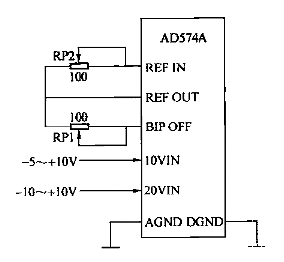
The AD574A is a high-performance 12-bit successive approximation analog-to-digital (A/D) converter that can interface directly with an 8 or 16-bit microprocessor bus. The input to the AD574A can be either unipolar or bipolar. The unipolar analog input voltage range...
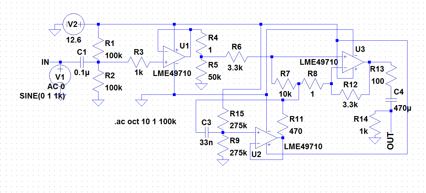
A circuit was required to function as a bass boost. The design was adapted from a circuit by ESP Sound, focusing solely on the frequency range of 35-150 Hz. The bass boost circuit, as adapted from the original design, primarily...
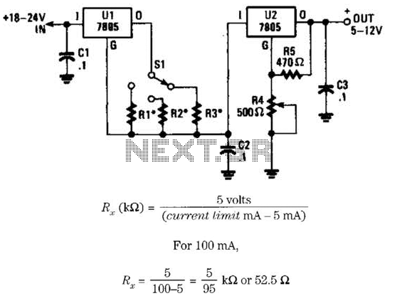
This voltage regulator and current limiter combination can be constructed using two 7805 regulators as illustrated. Resistors R1, R2, and R3 should be chosen to achieve a 5-V drop at the maximum allowable current limit. Switch S1 selects one...
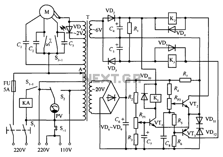
The circuit illustrated in the figure features an automatic voltage regulator (T) that utilizes a servo motor to ensure a constant output voltage. The transistors used are VT1 and VT2 (3DK9C, with a range of 65 to 85) and...
A company has developed an intelligent temperature monitoring system using the ATMET 89C51 microcontroller. This system automatically records temperature data for a three-phase power supply, including high temperature and other relevant data, functioning as a black box. The ATMET...
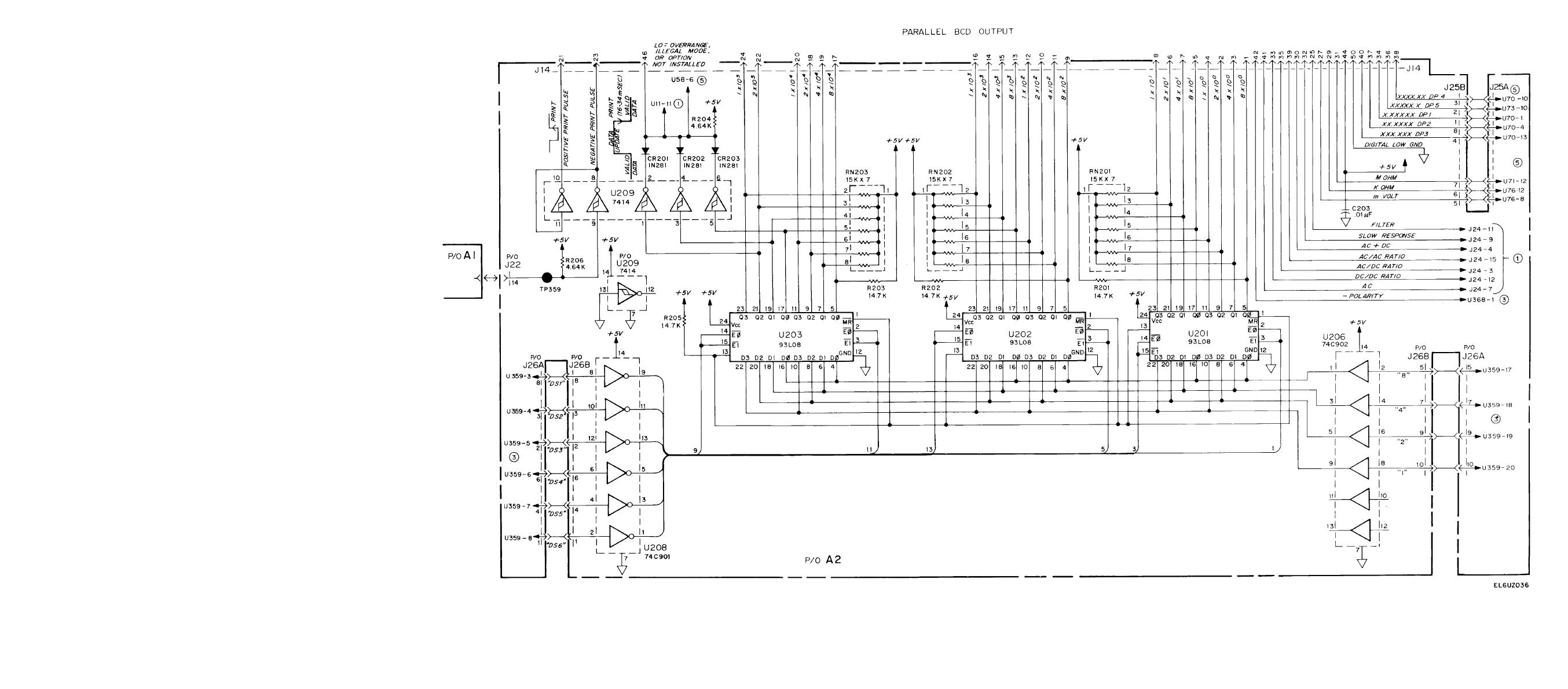
The definition of ecotherm insulation is crucial, particularly regarding its application in circuits. This includes the use of half adders in parallel adder configurations and the logic connection diagrams for parallel BCD (Binary-Coded Decimal) systems. A proper understanding of...