
humidity sensor circuit II
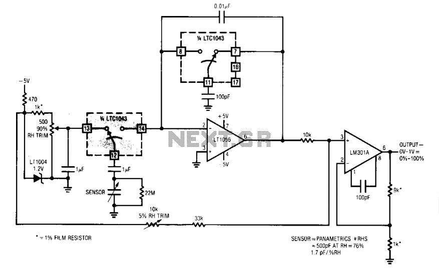
The circuit operates by utilizing a pair of switches, specifically the 14B-12B pair, which controls the connection of the sensor to the summing point of an operational amplifier (labeled as Al). When the switches are opened, the sensor's output is routed through a 1 µF capacitor, allowing the sensor's discharges to influence the summing point. This capacitor serves as a coupling element, ensuring that only AC signals are passed while maintaining a zero average voltage. This is critical for accurate readings, as it prevents any DC offset from affecting the sensor's output.
The average current flowing into the summing point is directly influenced by the humidity-related value of the sensor, which alters the amount of charge delivered over time. This current is balanced by the operation of a switched-capacitor circuit, which effectively integrates the incoming charge packets. The use of a 22M resistor in parallel with the summing point plays a vital role in preventing charge accumulation. If charge were to build up, it could halt the current flow, leading to erroneous readings and circuit malfunction.
The combination of these elements results in a system where the output from the operational amplifier reflects a DC signal that corresponds to the integrated average of the sensor's output. This integrator-like response is essential for applications requiring stable and accurate humidity measurements, as it smooths out fluctuations and provides a reliable representation of the sensor's performance.When the 14B-12B pair opens, 12B is connected to Al's summing point via 13B. The sensor now discharges into the summing point through the 1 µ capacitor. Since the charge voltage is fixed, the average current into the summing point is determined by the sensor's humidity related value. The 1 µ value ac couples the sensor to the charge-discharge path, maintaining the required zero average voltage across the device.
The 22M resistor prevents accumulation of charge, which would stop current flow. The average current into Al's summing point is balanced by packets of charge delivered by the switched-capacitor gives Al an integrator-like response, and its output is dc. 🔗 External reference
Related Circuits
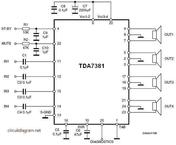
The TDA7381 is a Class AB audio power amplifier housed in a Flexiwatt25 package, specifically intended for car radio applications. This circuit can also be utilized for various other purposes. The fully complementary PNP/NPN output configuration enables a rail-to-rail...
This audio noise filter circuit functions as a bandpass filter specifically designed for the audio frequency range. It effectively filters out unwanted signals that fall below or above the desired audio frequencies. The circuit comprises two filters: a low-pass...
The LM317T is an adjustable three-terminal positive voltage regulator that can supply over 1.5 amps with an output voltage range of 1.25 to 37 volts. It features built-in current limiting and thermal shutdown, making it highly reliable and resistant...
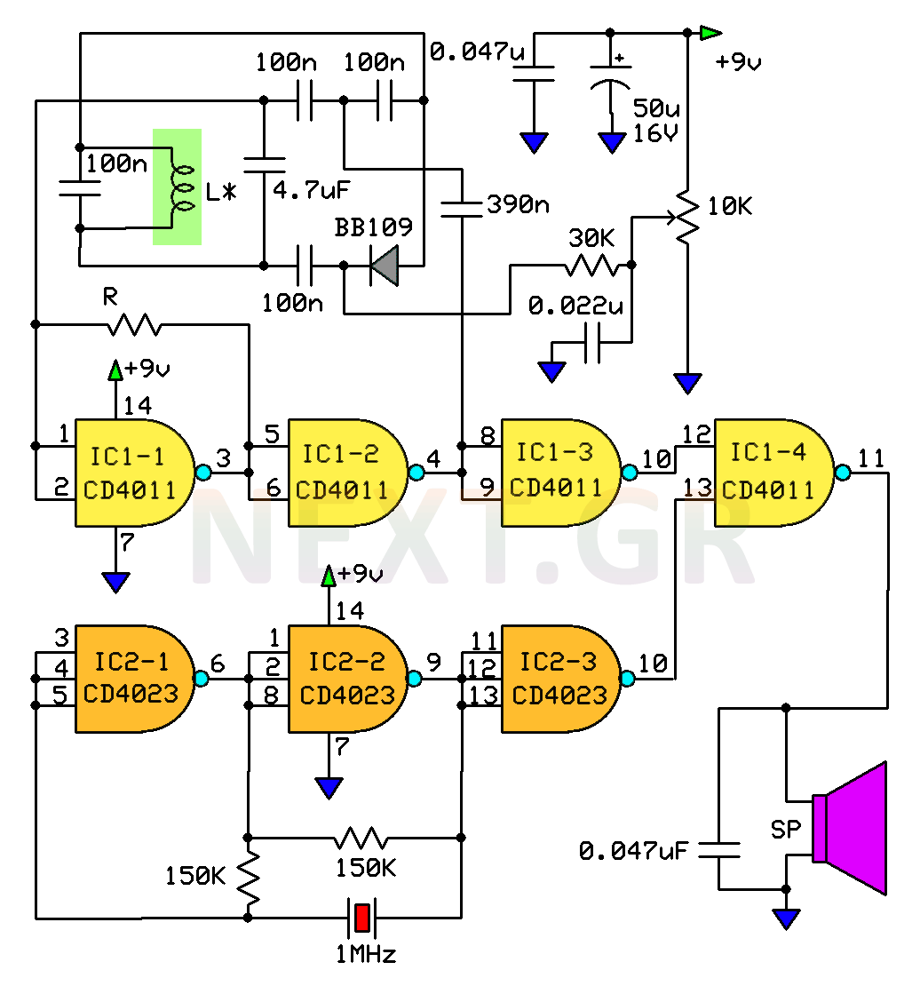
This circuit is a metal detector designed to detect large metallic objects at depths ranging from 2 to 3 meters, depending on the size of the object and the type of soil. The construction is straightforward, making it accessible...

Although analog and digital controllers may seem vastly different, their principles of operation are often quite similar. Therefore, popular analog tools like Spice can still be utilized to enhance common digital proportional-integral controllers through analysis, without the need for...
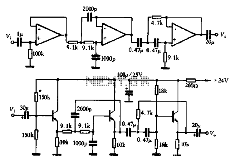
A band-pass filter is presented as a single-channel circuit diagram in this article, specifically for audio applications. The filter has a high cutoff frequency (fH) of 50 Hz and a low cutoff frequency (fL) of 13 kHz, as illustrated...