
Induction Balance Gold Metal Detector Circuit


The electronics required for construction are relatively straightforward and consist of conventional components, many of which may already be available. The electronic section comprises a pulse generator (transmitter) and a corresponding one-way receiver, utilizing two coils for signal processing.
The transmitter is based around IC1, where a low-power CMOS 555 timer generates a square wave output signal with a nearly 50% duty cycle and a frequency of about 700Hz. In astable mode, the output frequency is determined by resistors R4, R3, and capacitor C3. The output pulse is transmitted to the L1 coil through the R8-C4 network, with the electrolytic capacitor blocking DC and the resistor protecting the output stage of the 555. The pulse fronts from the 555 stimulate the coil, leading to intermittent oscillations at approximately 10kHz.
Before reaching the receiver unit (IC2), a simple parallel pre-amplification stage using IC3 boosts the signal received at the RX coil via components C11 and R9. The output amplifier's gain is adjustable using potentiometers P1 (coarse adjustment) and P2 (fine adjustment). The second CMOS 555 in circuit IC2 functions as a threshold detector, with its output switching to a high level when the input voltage drops below 1/3 of the supply voltage (around 2.9V) and reaching a low logic level when the voltage exceeds 2/3 of the supply voltage (approximately 7.4V). When the threshold is exceeded, a 700Hz signal is emitted from the piezoelectric buzzer, making the threshold setting a critical aspect of the circuit.
The RX and TX coils are designed for sensitive coupling, where the presence of metal disrupts their coupling and affects the threshold detector's calm state. Both coils are identical in size and partially overlap, allowing them to collect both positive and negative (inverted) magnetic field components generated by the TX coil. This careful balancing results in a theoretical zero signal at the output. However, practical limitations may introduce a small waste stream. When a metal object enters the field, it absorbs energy from the magnetic field, causing the RX coil to output a larger current, which exceeds the electrical threshold set in IC2, activating the buzzer. Optimal tuning of the detector is achieved when the absence of metal results in a mild whistling sound from the passive piezoelectric buzzer. When a metal object is detected, the sound level increases significantly, emphasizing the importance of correctly setting the coils' zero point.
Power for the circuit can be supplied by a 12V battery, an array of 8 AA batteries, or suitable rechargeable cells. A shoulder-mounted power pack is recommended to reduce the overall weight of the device and facilitate easy replacement when depleted. The IC4 voltage stabilizer is configured via resistors R1 and R2 to output 8.6V, with a current consumption of approximately 20mA depending on the buzzer's condition.
The construction of the circuit board is straightforward, as the available space is ample and all components have terminals. Care should be taken to ensure that the parts list corresponds with the layout printed on the board. The potentiometer axes are passed through the board to facilitate knob fitting after cutting to the appropriate length for the enclosure. A metallic enclosure is recommended for sensitive circuits to allow grounding of the potentiometer housing.
The two coils are constructed from enameled copper wire of 0.26mm diameter, wound into 100 right-handed spirals with a 15cm diameter. The wire diameter can vary between 0.2mm and 0.3mm. The coils are temporarily secured with insulating tape and then wrapped with insulating tape around the periphery, followed by the addition of a Faraday cage made from thin aluminum strips or foil. The ends of the aluminum foil must not touch to avoid short-circuiting the coil, which would introduce unwanted noise.
Each coil is connected with high-quality symmetrical shielded microphone cable, ensuring that the Faraday cage is grounded to the cable shield. Caution should be exercised when selecting the cable to avoid interference between coils. The coils are then wrapped with insulating tape and secured with absorbent cloth, which assists when applying resin to encapsulate the coils.
Once the coils are shaped and positioned, they should be overlapped, ensuring proper orientation. The coil support is constructed from a hard, non-metallic base using plastic resin, with wooden pins serving as walls to contain the resin. The coils are positioned to achieve a balance where the buzzer remains silent. The gain potentiometers should be adjusted to facilitate this balance, ensuring that the detector operates reliably.
The final assembly includes securing the coils in place and ensuring proper shielding to minimize interference. The detector is calibrated by adjusting the gain potentiometers while observing the buzzer's response to metal objects. Regular adjustments may be necessary due to environmental factors and soil composition.
An alternative construction method involves using plexiglass for the search head, where the coils are embedded in grooves on semicircular pieces of plexiglass, providing a durable and adjustable platform.
In practice, users will find that the detector's performance is influenced by soil metallic content, temperature, and voltage fluctuations, necessitating ongoing adjustments to maintain optimal functionality. The circuit's design allows for effective discrimination against iron, making it particularly advantageous for those seeking gold or precious metals.
Components list:
Resistances:
- R1 = 2.7kΩ
- R2 = 470Ω
- R3, R5, R6 = 100kΩ
- R4 = 4.7kΩ
- R7 = 1kΩ
- R8, R9 = 100Ω
- P1 = 50kΩ potentiometer
- P2 = 2.5kΩ potentiometer
Capacitors:
- C1 = 100µF / 25V electrolytic
- C2 = 47µF / 10V electrolytic
- C3 = 10nF
- C4, C6 = 10µF / 10V electrolytic
- C7-C11 = 100nF
Semiconductors:
- D1 = 1N4001
- IC1, IC2 = 555C, TLC555, 7555 (CMOS)
- IC3 = TL071CP, TL081CP
- IC4 = LM317 (CT220)
Other:
- K1, K2 = 3-pin terminal block, 5mm terminal block
- BZ1 = passive (AC) piezoelectric buzzer
- PC1, PC2 = board studs
- 12V battery or 8-cell AA battery pack
- Reinforced copper wire diameter 0.2-0.3mm, 2x50 meters
- Box dimensions: 109 x 58 x 25 mm, 5m symmetrical
- Shielded microphone cable (two lines with common shielding)This circuit really is the simplest inducer balancing metal detector (IB, Inductlon Balance) that can be built. The LB metal detection method has a satisfactory depth of penetration and good distinction between iron-based and noble metallic objects.
Several metal detectors are available in the market, but their price is often prohibitive for seekers looking for buried treasures. This detector is carefully constructed and properly configured to accurately detect a 15mm diameter brass coil 70mm in air or a coin of 25mm diameter at 120mm.
Even at a distance of 25% more, the detector will give unclear signs of coinage. Of course the ability to locate coins in the soil depends on the conditions of the ground between the treasure and the search head, with the ideal material being the dry sand and worse the mud and, of course, the size of the object.
The Electronics
The set of electronics required for the construction is relatively simple and is based on conventional components, most of which may already be on the warehouse. The electronic part consists of a pulse generator (transmitter) and the corresponding one-way receiver where two coils are used as a means of processing.
The transmitter develops around the IC1.
The (low power) CMOS 555 generates a square wave output signal with a pulse ratio of nearly 50% and a frequency of about 700Hz. With 555 in unstable operation, the output frequency is determined by the R4, R3 and C3 components. The output pulse is applied to the L1 coil through the R8 - C4 array, in which the electrolytic capacitor prevents DC from passing through the coil and the resistor protects the output stage within the 555.
The pulse fronts generated by the 555 stimulate the coil and cause intermittent oscillations at the same frequency of approximately 10kHz.
Prior to the receiver unit (IC2) there is a simple yet parallel pre-amplification step which is based on the IC3 booster amplifier and amplifies the signal received at the receiver coil (RX) via the components C11 and R9.
The gain of the output amplifier is regulated by potentiometers P1 (roughly) and P2 (accurately). The second CMOS 555 of circuit IC2 is connected so as to act as a threshold detector, the output of which (terminal 3) switches to high level input voltage (terminal 2) drops below 1/3 of the supply voltage (or about 2.9 V).
Similarly, the output reaches a low logic level once the voltage at the THR input (terminal 6) exceeds 2/3 of the supply voltage (or about 7.4 V). Thus, if the carefully set threshold is overcome, a 700 Hz signal will be heard from the piezo-electric beeper.
This threshold setting is particularly critical and is the key point of the circuit.
Coupling coils
The RX and TX coils are in a very sensitive coupling so that the presence of some metal disrupts their coupling and along with this carefully set the 'calm' of the threshold detector. The two coils are of the same size and have a partial overlap. This overlay gives the coil the ability to collect both a positive and a negative (inverted) percentage of the magnetic field generated by the TX coil.
Due to the careful balancing of the coils, the positive and the negative signals are mutually eliminated, resulting in the coil displaying at the output (theoretical) zero signal. The situation is called 'zero'. Nevertheless, due to practical limitations, there is a small waste stream. Once the sensitive equilibrium between the fields is disturbed by the presence of a metal object (which will absorb energy from the magnetic field), the coil RX will begin to provide the output with a larger current causing the electrical threshold set in IC2 to be exceeded and the Buzzer will start sounding In practice, the best tuning of the detector is achieved at the limit where the metallic object is absent, the passive piezo-electric buzzer produces a mild whistling sound.
With this setting, when a metal object enters the field the sound level will increase significantly. Setting the 'zero' point of the coils is particularly important.
Circuit power can be supplied from a 12V battery, or from an array of 8 AA batteries, or from the corresponding rechargeable cells. Whichever final form of feed is, the use of a power pack that we carry on the shoulder and is separate from the detector serves a lot because it reduces the final weight of the device while also enabling the package to be directly replaced when it is emptied.
The Ic4 voltage stabilizer on the board is set via R1 and R2 to provide an output voltage of 8.6 V. The current consumption of the battery pack is of the order of 20 mA depending on the condition of the buzzer.
Construction - the board
Fixing the components on the board is not expected to pose any problems because the available space is comfortable and secondly all the components used have terminals. Beginners should pay close attention to the correspondence between the parts list and the layout outline printed on the board.
The axes of the potentiometers are passed through the board. This fixation mode was chosen to facilitate the fitting of the appropriate knobs on the shafts when they are cut to the appropriate length depending on the box that will accommodate the circuit. Because we are dealing with a relatively sensitive circuit, we recommend the box to be metallic. In this way it is also easy to ground the potentiometer housing via the fixing nuts.
Construction - detection coil and assembly
The two coils are identical.
If it is not difficult to buy them, we can use enameled copper wire of 0.26mm. With which we will make 100 right-handed spirals in a circular form of 15cm diameter. The diameter of the wire is not critical and anything between 0.2mm and 0.3mm is OK. Then we temporarily fix the thread with pieces of insulating tape which we pass underneath and fasten from above. We also manufacture a similar coil, and once we finish, we tightly wrap the coils across the periphery with an insulating tape.
Then we need to add to each coil a Faraday cage.
This is achieved by means of thin and long strips of aluminum or foil wrapping. First we remove the varnish from the cable at the edge of each coil. Next, stick 100mm of bare cable to the base, and rotate it around the coil above the insulating tape.
This particular wire will provide electrical contact to the Faraday cage.
Starting from the bottom of the duct, wrap the foil around the circumference of the coil so that no part of the insulating tape is visible under the aluminum but the aluminum foil should not complete a full circle of 360 degrees. Leave a small gap before we get to the point where we started (about 10mm) so that the two ends of the aluminum foil do not come in contact, otherwise we will have a short-circuited winding around the coil which will introduce an awful amount of unwanted noise.
We do the same job on the second coil.
Then connect each coil with a good quality symmetrical shielded microphone cable where the Faraday cage is connected to the cable shield. Here we need attention to the choice of cable, it does not serve to use a stereo microphone shielded cable, as it may cause interference between the coils.
The cable type we need has two twisted wires internally surrounded by a common shield braid. Each coil is now wrapped tightly with an insulating tape across the periphery, and ending wrap around each coil with stripes of absorbent cloth (like the one that wipes the dishes) by fastening it with a little glue for general use. When we later pull Resin onto the coils, the cloth will help them swim in Resin
Carefully bend the two finished coils so they are relatively flat and circular, and we bring each ending wire opposite us and right of the start-up cable.
Then we bend them even further until they form asymmetric deficiencies as capital D. The backs of D are placed on the search head in such a way that they are partially overlapped and here is the most critical point of construction, which we will move on after completing the assembly of the board. And here we will need to shield the coils to make sure they only respond to their own magnetic field and limit the risk of inducing other signals (even caused by a minimal capacitive link).
Defective or inadequate shielding will result in sharp IC2 pulse fronts that will reach directly at the IC3 input. These parasitic pulses make it impossible to locate the 'null' point in the search coil.
Circuit setting
The construction of the detection head has not yet been completed, some components are already beginning to interact with the circuit settings.
Before we start fixing the coils, it is necessary to have a complete and functional board. The coil support is made on a hard non-metallic base, with the help of plastic Resin. As a base we can use any surface of suitable size whose walls are made of wooden pins of 5 mm in diameter perpendicularly glued. Note that these walls should be leakproof (do not leave Resin), while we should not use any metal. A portion of the 4cm coil protects it from being covered by Resin and can bend it if necessary for a final adjustment.
Initially, we place the coils one above the other, making sure that they are properly oriented, with the end of the wire facing us and to the right of its origin.
Turn the full-left gain potentiometers (minimum gain) so as to limit the amplification as much as possible. We connect a 12 V battery and feed the circuit. Then we slowly move the coils away from each other until the buzzer is calm.
At this point the voltages within the coil RX are zero and we continue to increase the gain slightly and moving the coils slightly.
We repeat the process several times, increasing the gain every time. The higher the gain, always having the ability to locate the zero point, the more reliable the detector will be.
Attention always drives the coils from full contact to full separation. If we set the system upside down, once a metal object is detected, the signal level within the coils will initially fall through zero and then rise again to reach the point where the buzzer will start to sound.
At the operating principle level there is no problem, only the detector will be very unconscious.
When searching for the optimal relative position between the coils we should show great patience. In case of need we can also use some wooden clamps for easier adjustment and comparison of the results.
Once we have spotted the exact points where the coils should be stabilized, we mark with a marker holes around and from the two coils. These holes serve to pass small wires that will tighten the coils on the support, and we will also need plastic cable ties to fasten the microphone wires to the same base.
Before removing the Resin, carefully seal the gaps under the base, as plastic Resin may exhibit too low viscosity and collapses much faster than other adhesives.
Carefully bend the coils at the center of the base until we reach the exact equilibrium point where from the buzzer (or headphones) we have neither complete peace nor noise, but a simple whistle. A slight shift at this point is not a problem.
Here we might be able to attach a rotating hinge to which the metal detector shaft will later be attached.
For a shaft we can use a 40mm or 50mm diameter PVC pipe like the one we use in the kitchen drain.
Now we are ready to mix and roll Resin It is good to use the right amount of catalyst so we do not have much heat or too much shrinkage of Resin. Pour the Resin onto the cloth surrounding the coils so that it soaks and we continue to pour Resin at least until the entire base is covered.
At this point and until the Resin hardens, the circuit may not work properly, so for now we do not make any further adjustments, but just switch off the circuit.
As soon as Resin hardens, we bring the search head away from any metal, as well as any device that can cause interference and supply the circuit. Turn the P2 potentiometer (precision setting) halfway through it. And then we turn the P1 (resonance) until the detector produces a slight whistle, something limiting between calm and noise.
For any further adjustment, we play with P1 and P2. Then we move a coin in front of the search head, so the piezo buzzer should start to sound.
Alternative construction method
The images illustrate an alternative method for implementing the search head, based on the use of plexiglas. The coils TX and RX are embedded in grooves drawn at the ends of separate plexiglass semicircles.
A third piece of plexiglass (this time square) serves to support the semicircle on it, connects to the PVC tube and still allows adjustment of the coils.
The last action is achieved with the help of plastic screws, since this construction is completed and mechanically adjusted, and it must swim in Resin so as to ensure the necessary durability and durability.
Use in practice
It is soon perceived to the user that the regulation of the metal detector is affected by the metallic elements of the soil it is investigating, as well as by the temperature and voltages, so the continuous adjustments of P1 and P2 are inevitable. A part of the extraordinary simplicity of the circuit is the partial slip that it presents, which although not excessive, necessitates a relatively regular adjustment of the detector.
At the center of the search head, the rejection of the circuit in the iron is too high, so when one acquires the necessary familiarity with the detector, practically he is able to exclude the iron.
This is an awesome advantage for those who use the detector to find gold coins or noble metals.
Components list
Resistances:
R1 = 2k7
R2 = 470O
R3, RS, R6 = 100 kO
R4 = 4k7
R7 = 1 kO
R8, R9 = 100O
P1 = 50KO potentiometer
P2 = 2K5 potentiometer
Capacitors:
C1 = 100µF / 25V electrolytic
C2 = 47µF / 10V electrolytic
C3 = 10nF
C4, C6 = 10µF / 10V electrolytic
C7-C11 = 100nF
Semiconductors:
D1 1N4001
IC1, IC2 = 555C, TLC555, 7555 (CMOS)
IC3 = TL071CP, TL081CP
IC4 = LM317 (CT220)
Other:
K1, K2 = terminal 3-pin terminal block, 5mm terminal block
BZ1 = passive (ac) piezoelectric buzzer
PC1, PC2 = board studs
12V battery or 8-cell AA battery pack
Reinforced copper wire diameter 0.2-0.3mm 2x50 meters
Box: (109 x 58 x 25 mm) 5m symmetrical
Shielded microphone cable (two lines with common shielding)
Related Circuits
If a page name is not selected by pressing the button, the previously selected page name continues to be used. The value is stored in EEPROM and may be changed at any time. When the unit is first powered...
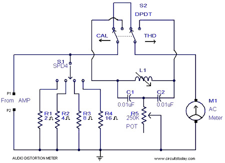
This is a simple 1 kHz audio distortion meter designed to measure the Total Harmonic Distortion (THD) on any load at any output power. The circuit allows for the selection of load impedances of 2, 4, 8, or 16...
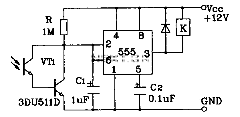
Darlington phototransistor type light-sensitive switch control circuit application. The Darlington type phototransistor serves as a sensitive element, capable of detecting low light levels for the detection of reflected light signals. The Darlington phototransistor circuit utilizes a pair of transistors configured...
The following circuit diagram depicts a variable power supply controlled by a PIC microcontroller. An LCD display is utilized to show the actual output current and voltage values. This digital power supply incorporates a push-button switch to adjust the...
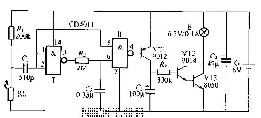
A battery-powered light control circuit is designed to delay the lighting of a small lamp during sudden power outages or nighttime situations when a blown fuse leaves a room in darkness. This circuit addresses the difficulty of locating matches...
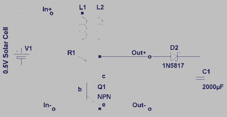
A steam engine-powered carousel project that utilizes the Joule Thief circuit. This project combines the classic charm of a steam engine with the innovative Joule Thief circuit, creating a unique carousel that operates efficiently. The steam engine serves as the...