
One-chip radar detection circuit

The X-band radar detector circuit operates by detecting RF radiation and converting it into a usable signal. The detector diode is the initial sensing element, which responds to incoming RF radiation. When RF energy is present, it generates a small voltage proportional to the radiation strength. This voltage is fed into a variable gain amplifier, allowing for sensitivity adjustments to ensure that the detector can operate effectively across various environmental conditions.
The output from the amplifier is then routed to a voltage comparator. This comparator compares the amplified signal against a preset threshold value that can be adjusted to prevent false triggering. The threshold is critical, as it determines the minimum level of RF radiation required to activate the warning system. The comparator's output is binary, providing a high signal when the input exceeds the threshold and a low signal otherwise.
In addition to the comparator, the circuit includes an oscillator configured to produce a square wave signal at a frequency of 2 Hz. This oscillator is connected in a wired-OR configuration with the comparator output. The wired-OR configuration allows for multiple signals to influence the output state. When no RF signal is detected, the comparator output remains low, which keeps the oscillator disabled and the lamp off.
Upon detection of RF radiation, the comparator output transitions to a high state, which releases the inhibition on the oscillator. As a result, the oscillator begins to operate, generating a square wave output that drives the lamp. The lamp thus flashes on and off at a rate of 2 Hz, providing a visual indication of the detected RF radiation. This flashing mechanism not only alerts the user to the presence of RF radiation but also serves as a clear warning signal that can be easily noticed.
Overall, this simple X-band radar detector circuit effectively combines RF detection, signal amplification, and visual indication in a compact design, making it suitable for various applications where RF radiation monitoring is essential.A simple X-band radar detector is capable of indicating changes in rf radiation strength at levels down to 2 mW/cm2. Radiation falling on the detector diode, produces a voltage at the input of an amplifier whose gain may be adjusted to vary the range at which the warning is given.
The amplifier output drives a voltage comparator with a variable threshold set to a level that avoids false alarms. The comparator output is connected in the wired-OR configuration with the open collector output of an oscillator running at a frequency of 2 Hz.
In the absence of a signal, the comparator output level is low, inhibiting the oscillator output stage and holding the buffer so the lamp is off. When a signal appears, the comparator output goes high, removing the lock from the oscillator which free-runs, switching the lamp on and off at 2 Hz.
Related Circuits
This circuit is designed to detect the approximate percentage of salt in a liquid. After careful calibration, it can provide a quick, rough indication of salt content in liquid foods for dietary purposes. The operational amplifier IC1A is configured...
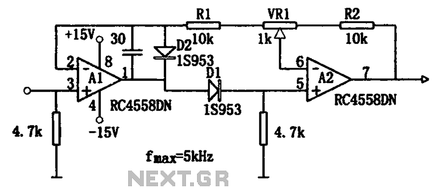
The circuit illustrates a simple method for adjusting the high input impedance of a double wave linear detector. It employs an operational amplifier configured with a negative feedback loop to compensate for the non-linear behavior of the diode used...
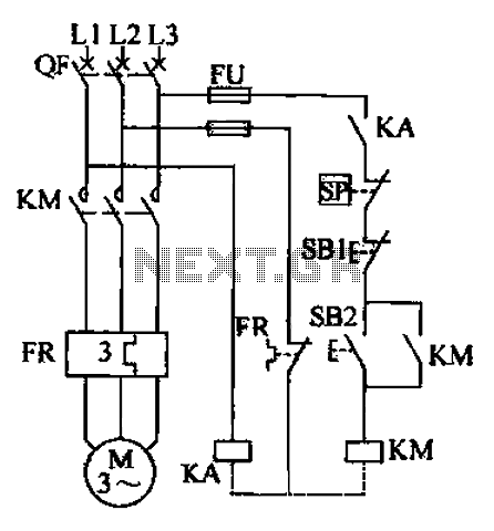
The air compressor control circuit operates based on several key principles. The first function is overload protection, which is facilitated by the thermal relay (FR). In instances of prolonged motor overload, the thermal relay activates to prevent overheating and...
Men, in particular, appreciate the convenience of television remote controls, which can often lead to frustration for their female partners. Men seem to have a desire to understand what... The initial statement highlights a common dynamic in household technology usage,...

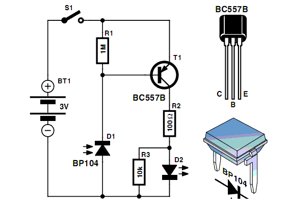
This FM transmitter (FM Tx) is about the simplest and most basic FM Tx it is possible to build and have a useful transmitting range. It is surprisingly powerful despite its small component count and 3V operating voltage. It...
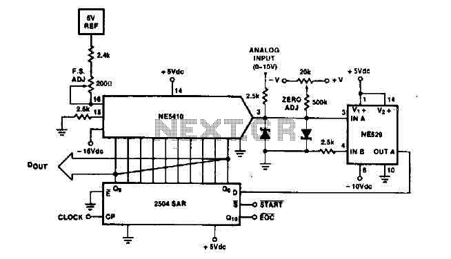
The time IO-bit conversion operates at 3.3 MHz with a clock signal. This converter utilizes a 2504 12-bit register in successive approximation mode, where the conversion signal for the short-cycle end is derived from the first bit utilized in...