
Phase sequence detector

The circuit utilizes three power solid-state relays (SSRs) to control the load based on the phase relationship between phase A and phase B. The primary function of this circuit is to prevent potential damage to the load that could occur due to incorrect phasing, which is a critical concern in three-phase systems.
In normal operation, when phase A leads phase B, the SSRs are activated, allowing current to flow to the load. This leads to the desired operation of the connected equipment. However, if the phase sequence is incorrect, specifically if phase A lags phase B, a cancellation effect occurs in the input currents. This cancellation prevents the necessary triggering of the silicon-controlled rectifier (SCR) and the inhibit SSR, which effectively isolates the load from the power source, thereby protecting it from damage.
The inclusion of the inhibit SSR is essential for maintaining electrical isolation at the input. This SSR serves as a safety mechanism, ensuring that under conditions of incorrect phasing, the circuit remains inactive, preventing any unintended operation of the load. The design of this circuit emphasizes reliability and safety, making it suitable for applications where phase integrity is critical.
Overall, the circuit provides a robust solution for managing phase relationships in three-phase systems, ensuring that loads are only energized under correct phasing conditions, thus enhancing the longevity and reliability of the connected equipment.This circuit prevents damage to the load due to incorrect phasing. The three power SSR's are only permitted to turn-on for a phase sequence of phase A leading phase B. If phase A lags phase the input currents will cancel, causing the SCR and the inhibit SSR to remain off until the sequence is reversed. The inhibit SSR is included to maintain isolation at the input.
Related Circuits
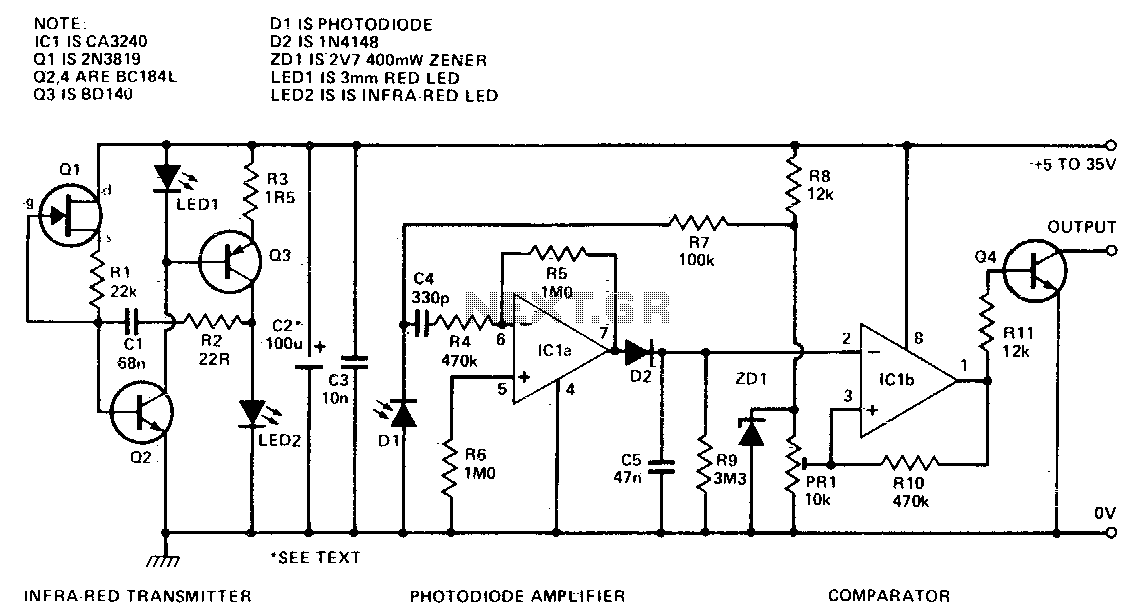
This circuit detects the presence of objects through the reflection of infrared light, providing a direct digital output for object detection. By utilizing modulation and high-power bursts of infrared light at a very low duty cycle, it achieves a...
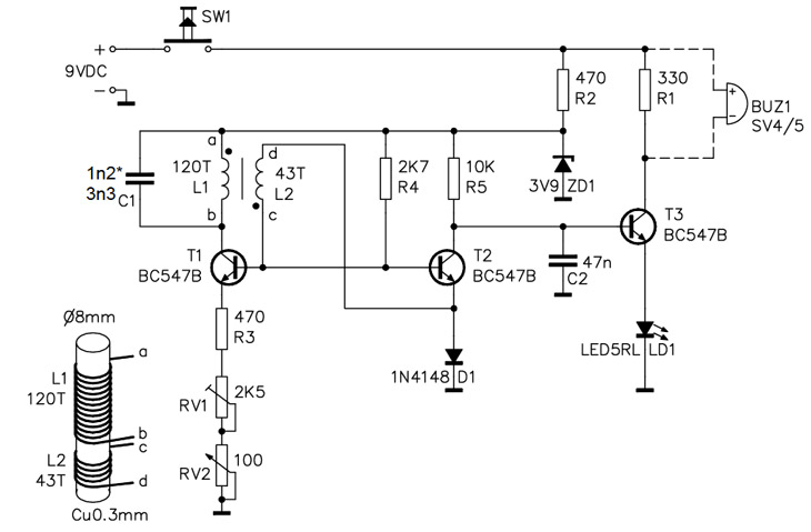
A simple home project can quickly become problematic if it encounters electric cables, gas, or water pipes, or the central heating system. Using a metal detector allows one to check for metal objects within walls, ceilings, or floors beforehand....
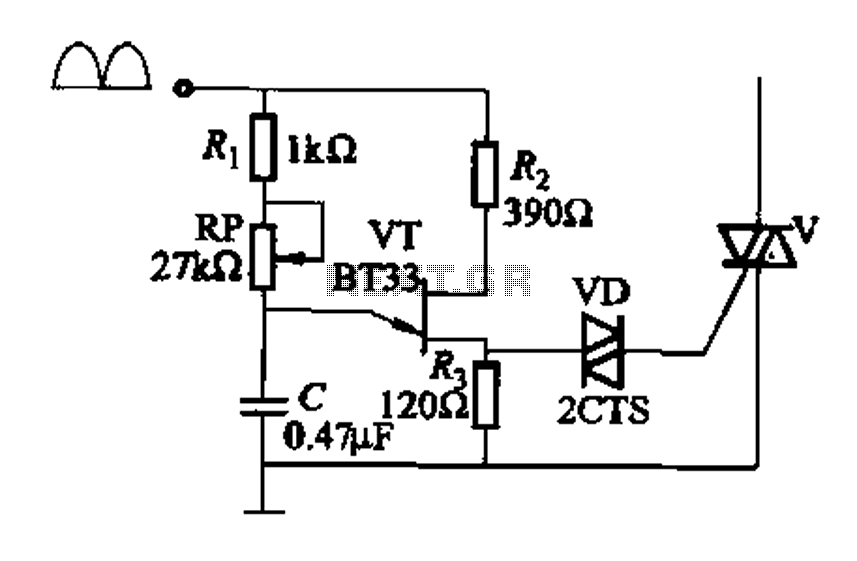
Figure 16-29 (a) illustrates the trigger output through a resistor R2, while Figure 16-29 (b) depicts the integration of a programmable unidirectional transistor (PUT) trigger circuit. The adjustable potentiometer RP can modify the conduction angle of the TRIAC to...
To sense and control the current in stepping motors and other similar devices, a linear integrated circuit such as the L6506 can be utilized. This chip set enables the formation of a constant current output. The L6506 is a versatile...
This is a very basic infrared detector/emitter circuit. One major downside of this circuit, is that ambient infrared light will interfere with its detecting obstacles. The described circuit functions as a basic infrared (IR) detector and emitter system, commonly utilized...
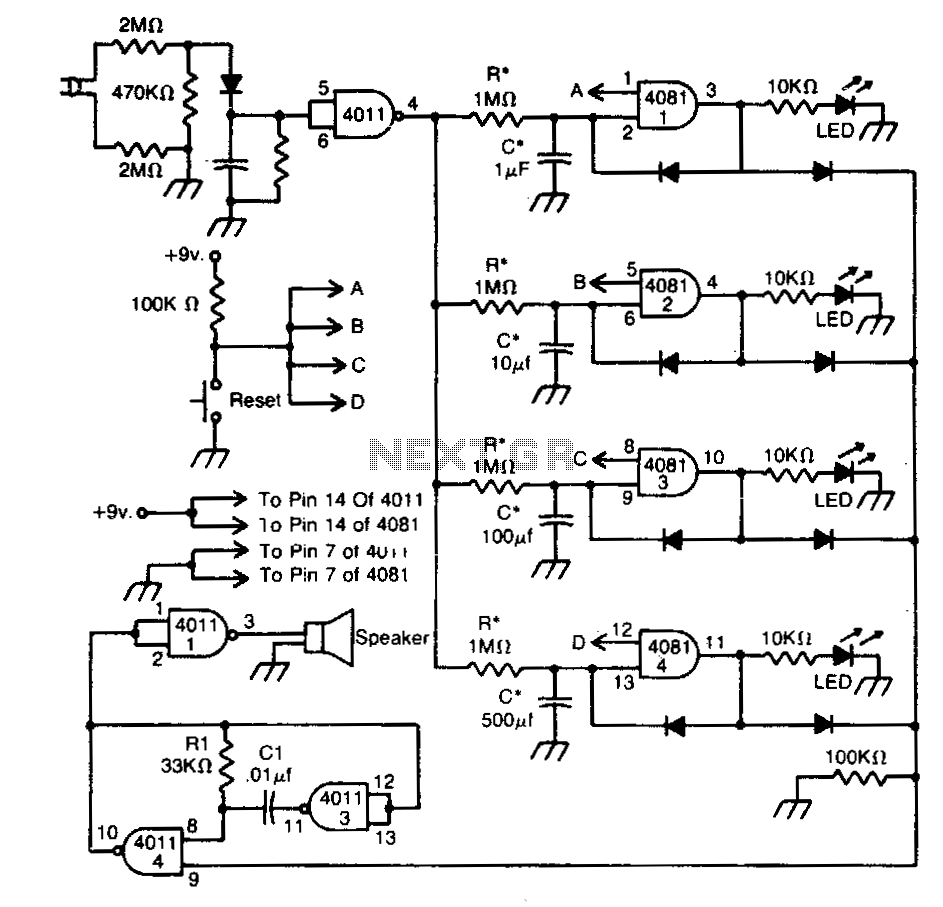
This circuit indicates that a power outage occurred for 1, 10, 100, and 500 seconds based on the values provided for R* and C*. After a power failure, the circuit can be reset by pressing the Reset button. The described...