
Sense automobile high-side current with discrete components

The presented circuit is a discrete current sensing amplifier designed to provide accurate current measurement while being straightforward to assemble. The use of Q2 as the primary current amplifier allows for an amplification factor of 6, enhancing the sensitivity of the circuit. Q1, as a temperature-compensated amplifier, is crucial for ensuring stable operation across varying environmental conditions. IC1B plays a vital role in maintaining the collector voltage of Q1, which is essential for consistent performance.
The reference voltage of 5V is derived from a stable power supply, which is critical for the integrity of the measurements. The schematic indicates specific voltage levels at various points, providing insight into the operational characteristics of the circuit. The design incorporates R3, which is constructed from two stacked surface-mount power resistors, ensuring that the circuit can handle high current levels without overheating.
The circuit's ability to accommodate a current input of 25A while producing a 5V output allows for direct interfacing with microprocessors, facilitating easy integration into larger systems. The recommendation to match resistors R6 and R7, as well as R1 and R4, highlights the importance of precision in resistor values to minimize discrepancies in performance. The choice of 1% tolerance resistors for most components underscores the need for accuracy in the circuit's operation.
To ensure the circuit's reliability, careful attention should be paid to the PCB design. Adequate copper thickness and trace width are necessary to handle the high currents involved without introducing excessive resistance or heat. Implementing Kelvin connections for R3 will further enhance measurement accuracy by reducing the impact of lead resistance.
Overall, this discrete current sensing amplifier circuit provides an effective solution for applications requiring accurate current measurement, particularly in scenarios where integrated circuits are not available. The thoughtful design considerations and component choices contribute to its robustness and reliability in practical applications.This Design Idea came about as a result of my not having access to those wonderful new ICs that sense current. I needed a discrete circuit that I could build easily but that would still be as accurate as the new ICs.
This circuit seems to do the job. Q2 is the first current amplifier; it has a gain of 6. 2 (Figure 1). Q1 is the temperature-compensa tion amplifier controlled by IC1B, which keeps the Q1 collector voltage constant no matter what the temperature does to the circuit. The reference voltage for the circuit is the 5V system supply. The voltages noted on the schematic are as built. R3 comprises two surface-mount power resistors, stacked one atop the other. The circuit has a range of 25A in for 5V out. This setup works nicely with an analog input to the microprocessor. If you want to get critical, match R6 and R7; more critical again, also match R1 and R4. I didn`t do this step, and the mismatch did not seem to affect the operation. All resistors except R3 are 1% 0805 SMT. Observe sufficient copper weight and width on your PCB traces for maximum current-carrying capacity, and be sure to use Kelvin connections to R3.
This circuit ran slightly warm to the touch at 25A. If you liked this feature, and would like to see a weekly collection of related features delivered directly to your inbox, sign up for the Design Ideas newsletter here: 🔗 External reference
Related Circuits
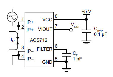
The primary component utilized is the ACS712 sensor from Allegro MicroSystems, designed for measuring current. It offers cost-effective and accurate solutions for AC or DC current sensing in industrial, commercial, and communication systems. A precise, low-offset, linear Hall sensor...
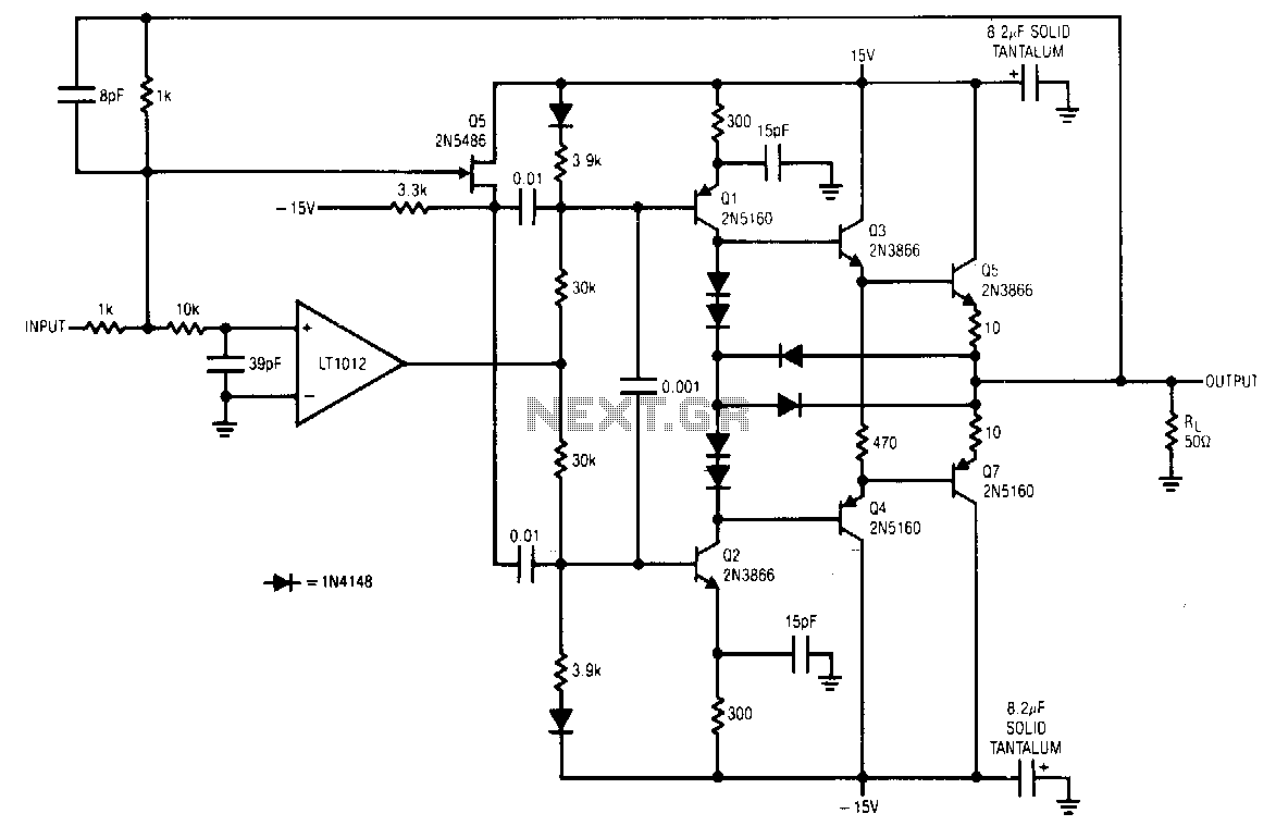
The LT1012 corrects errors in the booster stage and does not set high-frequency signals. Fast signals are fed directly to the stage via Q5 and the 0.01 µF coupling capacitors. DC and low-frequency signals drive the stage via the...

A current source that achieves a resolution as low as 10 pA is beneficial in applications requiring precise, low-value currents. When the circuit directs current into the ground, the output remains within 2% of the ideal current across the...
This circuit provides automatic current limiting up to 8.4 A. Unlike current limiters that use only a resistor, this current limiting circuit does not drop the voltage significantly or keeps the voltage drop to a minimum until a specific...
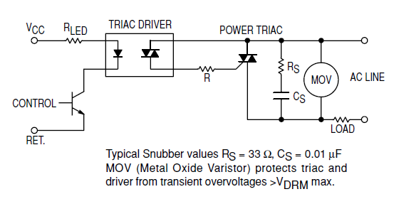
Interfacing the BT139-600 TRIAC with the MOC3051-M Opto-triac requires the construction of a snubber circuit as illustrated in the MOC3051M opto-triac's datasheet on page 8, figure 12. The load connected to this circuit will be a 230V AC, 4A...
This application example illustrates a photovoltaic control circuit. In this circuit, the Triac functions as a solid-state relay, providing an AC power supply path to the load. It is designed to achieve high current control signals using a small...