
Precise Low-Current Source

The described current source circuit is designed to provide precise low-current outputs, making it suitable for sensitive applications such as sensor interfacing and precision measurement systems. The core of the circuit relies on the OP80 operational amplifier, which is known for its low offset voltage and low noise characteristics, essential for maintaining accuracy in low-current scenarios.
The feedback mechanism is critical; U1A adjusts its output based on the voltage drop across R5, ensuring the current flowing through R5 aligns with the desired output. The choice of R5 is also crucial, as it directly influences the circuit's performance and noise characteristics. The unity-gain differential amplifiers (U1B and U2) serve to amplify the sensed voltage drop across R5 while maintaining a high degree of linearity and stability.
The compliance voltage range of -4 to +3.5 V indicates the limits within which the circuit can operate effectively without significant deviation from the expected performance. The 2% output accuracy within the ±100-nA range demonstrates the circuit's reliability in delivering a consistent current output.
Noise management is an important aspect of the design, particularly the 400 nV/kHz noise figure, which suggests that the circuit is optimized for low-frequency applications. This makes it less suitable for high-frequency applications, where noise can significantly impact performance.
For applications requiring higher bandwidth, it is advisable to adjust the resistor values or the reference current (i5), which will allow the circuit to operate effectively at higher frequencies while still providing adequate current resolution. Overall, this current source design exemplifies a balance between precision, stability, and noise management, making it a valuable component in various electronic applications. A current source that attains a resolution as low as 10 pA is useful in applications where a precise, low-value current is needed. When the circuit forces current into ground, the output remains within 2% of the ideal current over the ±100-nA range. Over the -4- to +3.5-V compliance range, the error that appears is less than 5%. This accuracy results from using an OP8O op amp from Precision Monolithics in the feedback loop. The OP8O has an IB of 200 mA typical. For a given voltage (V^), amp Ul A generates an output voltage so that the current through R5 equals V divided by i5 (10 ).
This current causes a voltage drop across R5, which is sensed by the unity-gain differential amp (U1B and U2). That amp"s output is connected to the inverting input of U1A, completing the feedback loop. The noise in the circuit is of particular concern, especially that produced by resistor R5. The circuit is limited to low-frequency and dc applications as a result of its 400-n V/kHz noise. For applications that don"t require the circuit"s 10-pA output, lower values of i5 can be substituted.
This will increase the bandwidth.
Related Circuits
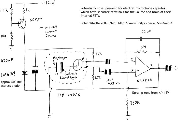
This circuit may be of interest to individuals designing preamplifiers for electret and externally polarized condenser microphones that lack an internal FET. If the noise from a single FET is a limiting factor, utilizing two or four FETs in...
This circuit is designed for the selection of alternative sources. It integrates mechanical selection through a rotating switch S1, electronic control of relays RL1 to RL10, and optical indication of the selection via the display DSP1. The circuit operates by...
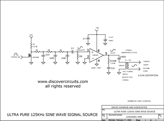
Ultra pure 125 kHz sine wave signal source. For certain RFID systems operating at 125 kHz, a very low distortion signal source is essential. The circuit presented here produces a 10-volt peak-to-peak signal. The ultra pure 125 kHz sine wave...
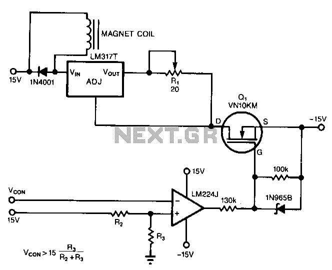
The circuit powers the load through the input of the regulator rather than its output. Due to the presence of a constant dummy load (R1) at the regulator's output, it attempts to draw a constant amount of current, regardless...
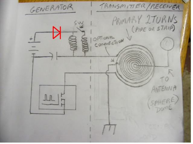
At approximately 50 kHz, a voltage exceeding 40 volts is observed at the receiver. LEDs illuminate without issues, although a 5mm LED was damaged. A capacitor connected to the AC was obstructing energy transfer. The primary negative was connected...
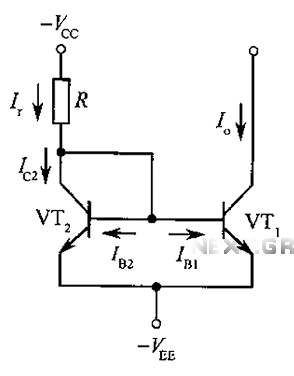
The circuit depicted is a mirror substantially constant current source circuit, in which transistors VT1 and VT2 are matched to each other. The figure illustrates that the current through Ir is equal to Ic2 plus the sum of base...