
sensitive FM Transmitter

The FM transmitter circuit is designed for simplicity and efficiency, making it suitable for hobbyists and educational projects. The core of the circuit consists of two transistors that facilitate the modulation of audio signals onto a carrier frequency. The use of ceramic capacitors, particularly of the NPO type, ensures stability and minimal drift in frequency, which is crucial for maintaining clear audio transmission. The circuit can function effectively with alternative capacitors, provided they are not electrolytic or tantalum, to avoid distortion and inefficiencies.
The FM tracking transmitter, which utilizes four transistors, expands upon this basic design and allows for more complex signal tracking and modulation capabilities. This feature makes it ideal for applications where precise frequency control is necessary. The components listed, including resistors and capacitors, are selected to ensure optimal performance across the specified frequency range.
The BEL1895-based shortwave transmitter circuit represents a more advanced application, allowing operation in the HF band. This circuit is particularly valuable for short-range communication projects and educational demonstrations of radio frequency transmission principles. The inclusion of a microphone amplifier, variable frequency oscillator, and modulation stages enhances the circuit's capability to transmit audio effectively over a distance.
The audio pre-amplifier circuit using the 2N3904 transistor serves as a crucial component in boosting weak audio signals. This pre-amplifier can significantly improve the performance of the RF transmitter by ensuring that the audio input is strong enough to modulate the RF signal effectively. The design allows for a straightforward integration with RF oscillators, making it an excellent choice for creating sensitive RF transmitters that respond well to audio input.
Overall, these circuits illustrate fundamental principles of radio frequency transmission and audio amplification, providing a practical and educational experience for users interested in electronics and communication technologies.Simple and easy build of FM transmitter circuit. The circuit only require 2 transistors. Circuit Notes: Typically the default for the capacitors model is ceramic, preferably the npo 1% type or equivalent. However, generally almost nothing critical right here. Work with any capacitor you`ve laying arround, but DO NOT use any electrolytic or tantal um. The following diagram is the FM tracking transmitter based on 4 transistors. No additional notes for this tracking transmitter diagram, try to discover this circuit by yourself. :) Components list: R1 = 100K Ohms R2 = 10 Ohms R3 = 47K Ohms R4 = 220 Ohms C1 = 4. 7uF/16V C2, C5 = 1nF C3 =. Here the SW transmitter circuit based on IC BEL1895. This particular transmitter circuit works in shortwave HF band (6 MHz to 15 MHz), and can be applied for shortrange communication and for educational purposes. The circuit is composed of a mic amplifier circuit, a variable frequency oscillator, and modulation amplifier stages.
Transistor T1 (BF195) is. This is a simple audio Pre-Amplifier with single transistor 2N3904. This easy circuit provides good gain to weak audio signals such as electret microphone. Use it in front of an RF oscillator to make an RF transmitter that`s very sensitive to sound. 🔗 External reference
Related Circuits
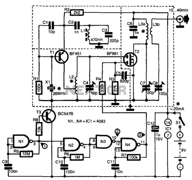
The transmitter is specifically designed for radio amateurs to function as a radio beacon, delivering a high-quality signal devoid of unwanted harmonics. Transistor T1, in conjunction with crystal X1, serves as a 36-MHz oscillator. Filter L1/C3 prevents the circuit...
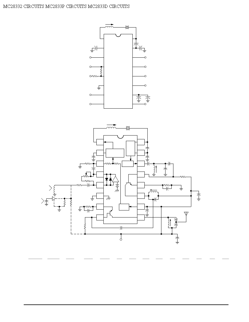
Crystal X1 operates in fundamental mode and is calibrated for parallel resonance with a load capacitance of 32 pF. The final output frequency is produced through frequency multiplication within the MC2833 integrated circuit (IC). The RF output buffer at...
This is an image Schematic. No Description available. The provided input indicates that there is an image schematic without a detailed description available. In typical electronic schematics, various components such as resistors, capacitors, diodes, transistors, and integrated circuits are...
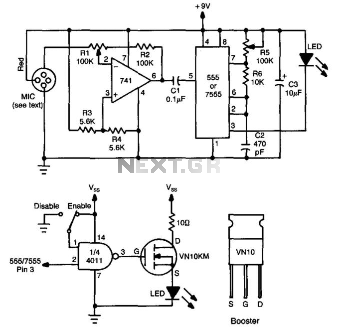
This circuit utilizes a 741 audio amplifier, which is connected to an amplified microphone, an FM modulator, and a CMOS timer functioning as a voltage-controlled oscillator (VCO). The timer output drives an LED, which is pulsed to produce an...
This PLL transmitter is digitally programmable, ensuring stable frequency operation. It operates within the 88-108 MHz range with an output power of up to 500 mW. With minor modifications, the frequency can be adjusted to 50-150 MHz, and the...

The game was originally designed to position three balls locked in holes on a slowly rotating ring around the Deadworld. Once the third ball was secured, a mechanical arm would release them, dropping the balls onto the playfield. This...