
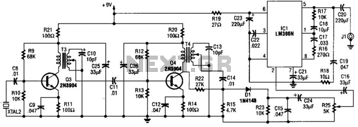
500mw pll fm transmitter 88 108mhz

The PLL (Phase-Locked Loop) transmitter is designed to provide a reliable and adjustable RF signal. The core of the system is the Colpitts oscillator, which is favored for its stability and simplicity in generating high-frequency signals. The oscillator's output frequency can be finely tuned using a combination of software commands and physical adjustments to the coil, which can be made from a compressed air setup to optimize performance.
The PLL circuit plays a critical role in maintaining the oscillator's frequency by comparing the output frequency to a reference frequency and making necessary adjustments. This feedback mechanism ensures that the output remains stable even in varying environmental conditions. The integration of a PIC microcontroller allows for digital programming of the frequency, enabling users to easily change the operational parameters without requiring extensive hardware modifications.
With an output power capability of up to 500 mW, the transmitter is suitable for various applications, including FM broadcasting within the designated frequency range. For applications requiring higher power, the use of transistors can elevate the output to several watts, providing greater range and signal strength. The versatility of this PLL transmitter makes it an excellent choice for hobbyists and professionals alike, facilitating experimentation and development within the radio frequency domain.
Overall, this PLL transmitter design merges modern digital control with classic analog techniques, resulting in a robust and flexible platform for frequency modulation and transmission.This PLL transmitter is controlled and the frequency is very stable and can be programmed digitally. Transmitter will work 88-108 MHz and output power up to 500mW. With a small change can set the frequency of 50-150 MHz. The output power is often set to several watts with transistors. So therefore I decided to build a simple transmitter with great performances. The frequency of this transmitter can easily be changed by software and space / compress air coil. This transmitter is the oscillator colpitts. Oscillator is a VCO (voltage controlled oscillator) which is set by the PLL circuit and PIC micro controller. This oscillator is called the Colpitts oscillator and voltage controlled to achieve the FM (frequency modulation) and PLL control.
🔗 External reference
Related Circuits
The FM Wireless Microphone has gained popularity among both beginners and experienced constructors. It has been utilized in guitars and as a component of remote control systems. There have been numerous requests for a higher-powered circuit with improved microphone...
The AM transmitter circuit consists of an audio amplifier and an RF oscillator. The oscillator is constructed around transistor Q1 and its associated components. The tank circuit, which includes inductor L1 and variable capacitor VC1, is tunable from approximately...
A PLL (Phase-Locked Loop) oscillator is utilized to achieve a very stable frequency with minimal distortion in the sine wave output. Its stability is comparable to that of crystal-based oscillators, while the distortion level of the sine wave output...
The 2.25-MHz oscillator Q1 drives amplifier Q2 and XTAL1, an ultrasonic transducer. The transducer is a lead zirconate-titanate type. Taps on T1 and T2 provide low-impedance drive points. The circuit consists of a 2.25-MHz oscillator (Q1) that serves as the...
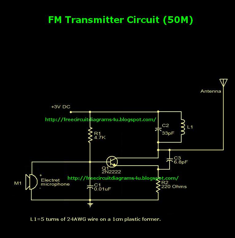
This is an FM transmitter circuit diagram. This circuit uses a 2N2222 transistor, allowing it to operate at 3V and transmit signals up to 50 meters. The FM transmitter circuit consists of several key components, primarily centered around the 2N2222...
This frequency of this transmitter is PLL controlled which makes it very stable. The frequency is programmed in digitally way and can be changed very easy. Frequency range is about 50 to 150 MHz and the output power 100mW....