
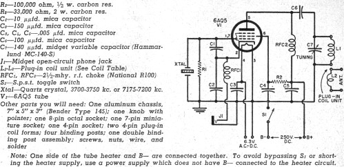
Sensitive FM Transmitter

The sensitive FM transmitter circuit is designed to operate in the frequency modulation range, typically used for audio transmission. The core components of this transmitter include an oscillator, modulator, and an RF amplifier.
The oscillator is responsible for generating a carrier frequency, which is modulated by the audio signal input. In this design, a crystal oscillator or a Colpitts oscillator can be employed to ensure frequency stability. The frequency of oscillation can be adjusted by varying the capacitance in the LC tank circuit, which is formed by an inductor and capacitors.
Capacitors play a vital role in tuning and stability. The recommended capacitors are ceramic, particularly the NPO type, which offers low drift and high stability over temperature changes. Using capacitors with a tolerance of 1% ensures that the frequency remains stable, although the circuit can function with other types of capacitors if necessary.
The modulator section combines the audio input signal with the carrier frequency. This can be achieved through a simple transistor-based circuit, where the base of the transistor receives the audio signal, causing variations in the collector current that modulate the RF signal.
An RF amplifier then boosts the modulated signal to a suitable level for transmission. This stage typically uses a class C amplifier configuration for higher efficiency. An appropriate antenna is connected at the output to radiate the signal effectively.
Power supply considerations are also crucial. The circuit may require a regulated DC supply to ensure consistent operation, with bypass capacitors placed close to the power pins of the active components to filter out noise.
Overall, the sensitive FM transmitter circuit is a versatile design that can be adapted for various applications, including hobbyist projects and educational demonstrations. Proper layout and component selection will enhance performance and reliability in practical implementations.Sensitive FM Transmitter. Additional Notes The default for the capacitors type is ceramic, preferably the npo 1% type or equivalent. But basically nothing critical here. Use any. 🔗 External reference
Related Circuits
This house FM transmitter for your stereo or any other amplifier provides a good signal strength up to a distance of 500 meters with a power output of about 200 mW. It operates on a 9V battery. The audio-frequency...
Although this CW transmitter circuit was published in 1955 in Popular Electronics, it remains legal for today's amateur radio operators. Portions of the 40-meter and 80-meter bands are still reserved exclusively for CW operation. As of 2011, the frequencies...
The circuit of AM transmitter is designed to transmit (amplitude modulated) DSB (double side band) signals. A modulated AM signal consists of a carrier and two symmetrically spaced side bands. The two side bands have the same amplitude and...
This set of two circuits forms the basis for a simple light wave transmitter. A laser beam is modulated and directed toward a receiver that demodulates the signal, subsequently presenting the information (voice, data, etc.). The assembly is straightforward and...
This circuit diagram is part of an RF circuit. It features an FM transmitter circuit diagram using the BH1417 integrated circuit from RHOM, which incorporates multiple functionalities in a compact design. The IC includes pre-emphasis and a limiter to...
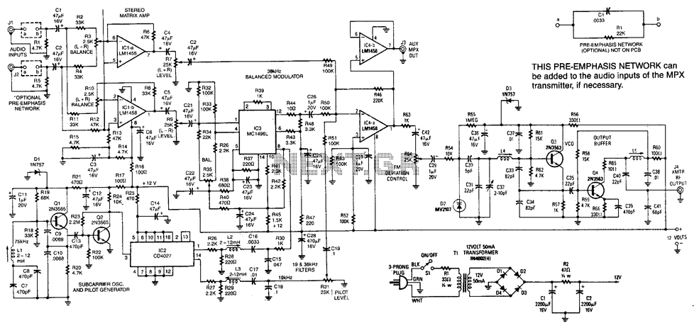
This transmitter has a range of up to 100 feet. It generates a complete multiplex stereo signal and is useful for cordless headphone applications in which an inexpensive socket stereo receiver can be used. It can also be used...