
dc motor controller circuit using 741

The described circuit involves a variable speed control mechanism utilizing a potentiometer and two power transistors, TIP3055 and MJE34. The potentiometer, labeled as VR1, acts as a variable resistor that adjusts the input signal to the transistors based on its position. When VR1 is turned, it changes the resistance in the circuit, which in turn modifies the voltage and current flowing through the connected load, effectively controlling the speed of the motor or device in question.
The TIP3055, an NPN power transistor, is capable of handling a collector current of up to 15A, making it suitable for high-power applications. Its maximum collector-emitter voltage (VCE0) rating of 60V DC indicates that it can operate safely within this voltage range without risk of breakdown. This transistor is typically used in the output stage of the circuit, where it amplifies the current to drive the load.
In contrast, the MJE34, a PNP power transistor, has a lower collector current specification of 10A and a VCE0 rating of 40V DC. This transistor may be utilized in the circuit to control the direction of current flow or to switch the power supply to the load, depending on the configuration of the circuit. The combination of the NPN and PNP transistors allows for efficient control of the motor speed in both directions, providing versatility in operation.
The overall design ensures that the speed control is smooth and responsive to user input, with the potentiometer providing fine adjustment capabilities. Careful consideration must be given to heat dissipation for the transistors, as they may generate significant heat during operation, particularly at higher currents. Proper heat sinking and thermal management techniques should be implemented to maintain reliability and performance of the circuit.As the potentiometer VR1 is moved toward either end, the speed increases in whichever direction it is turning. The TIP3055 Q1 NPN power transistor has a collector current specs of 15A and VCE0 of 60V DC. The MJE34 Q2 PNP power transistor has a collector current specs of 10A and VCE0 of 40V DC. 🔗 External reference
Related Circuits
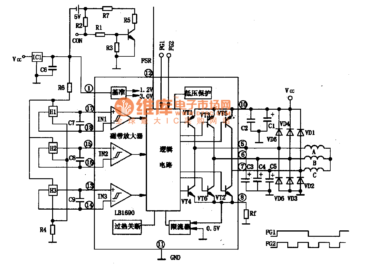
LBl690 is a three-phase brushless DC motor drive control integrated circuit manufactured by Sanyo, a Japanese company. It is extensively utilized in both domestic and imported applications for broken wind and fresh air conditioning systems that require brushless DC drive...
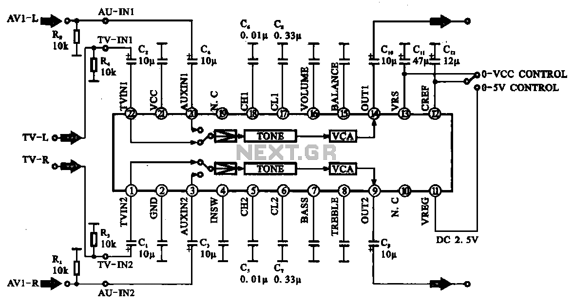
Audio signal control circuit. It illustrates a typical audio signal control circuit where two audio signals enter the integrated circuit through switching and tone controls (treble and bass), subsequently adjusting the output sent to the audio power amplifier. The audio...
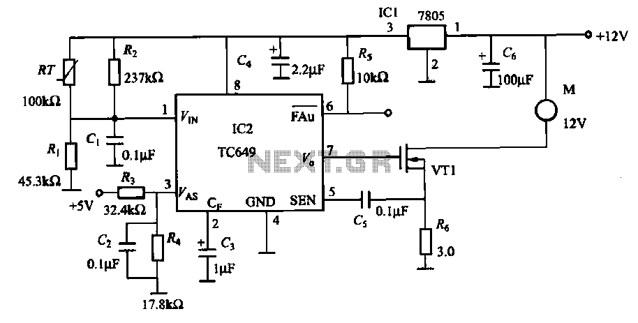
A motor is a heating device that can overheat, often due to accidents or overloads caused by excessive coil winding temperatures. The TC649 motor overheating protection and drive circuit, depicted in FIG. 1-9, utilizes an NTC thermistor (RT) positioned...
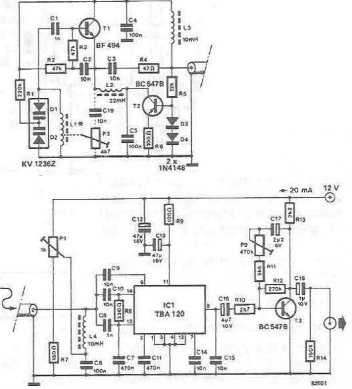
The tuning stage of this long-wave and medium-wave radio receiver also functions as an active antenna, which can be optimally positioned for the best reception. The circuit is completely independent from the receiver, which includes a demodulator that provides...
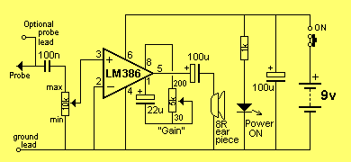
This mini audio amplifier will test the audio stages in amplifiers such as the front end of FM bugs. You can also use it on lots of our other projects as well as the output stages of radios. It...
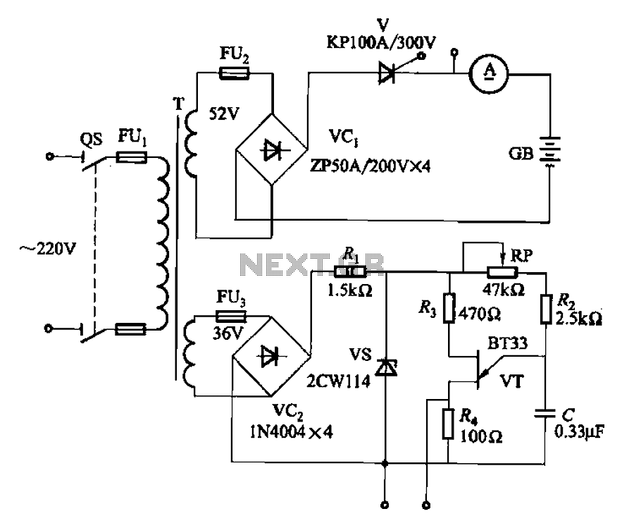
The adjustment potentiometer RP can modify the magnitude of the DC output voltage. The adjustment potentiometer, designated as RP, is an essential component in various electronic circuits, particularly in power supply systems and signal conditioning applications. It serves as a...