
Sensor Circuit Of Analog Line Follower Robot

The sensor circuit for an analog line follower robot is designed to detect the presence of a line on the ground, typically represented by contrasting colors, such as black and white. The primary components of this circuit include an array of infrared (IR) sensors, a microcontroller for processing sensor inputs, and motor driver circuits to control the robot's movement.
The IR sensors are strategically positioned to sense the line beneath the robot. When the robot is over the line, the IR sensors detect the change in reflected light intensity. This information is then relayed to the microcontroller, which processes the signals to determine the robot's position relative to the line. The microcontroller is programmed with algorithms that dictate how the robot should respond to the sensor inputs, allowing it to adjust its path accordingly.
The motor driver circuits are responsible for controlling the speed and direction of the motors based on the microcontroller's output. Typically, a dual H-bridge motor driver is employed to allow for bidirectional control of the motors, enabling the robot to turn left, right, or move forward and backward as needed.
Overall, the sensor circuit of an analog line follower robot is a crucial component that integrates sensing, processing, and actuation to achieve autonomous navigation along a predefined path. Proper calibration of the sensors and tuning of the control algorithms are essential for optimal performance of the robot in various environments.The following circuit shows about Sensor Circuit Of Analog Line Follower Robot. Features: controlled by a microcontroller, sensor circuit, a set .. 🔗 External reference
Related Circuits
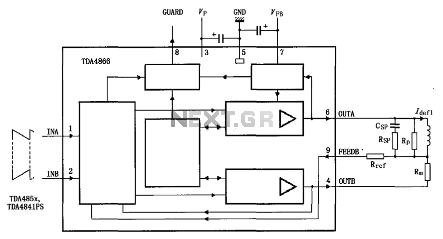
The TDA4866 is a 90-color power amplifier designed for vertical deflection systems, operating at a frequency range of 50 to 160 Hz. The CRMM circuit is implemented to ensure a high current drive input. The amplifier features a dual...

The TDA6106Q test circuit, as depicted in the provided figure, operates with a feedback factor of 1/116. The input signal, Vin, is received from the input network consisting of resistors R1, R9 and capacitors C1, C2. The TDA6106Q IC...
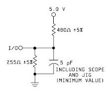
A device that conducts electric current and converts electrical energy into another form. Power consumed by a device or circuit while performing its function can be represented by a resistor and capacitor. The capacitor in the load circuit represents...
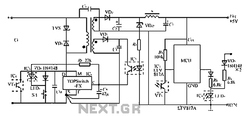
The circuit diagram of the TOPSwitch FZ chip switching power supply is controlled by microcontrollers (MCUs). The microcontroller can be utilized with inkjet printers, laser printers, and other computer peripherals. The TOPSwitch FX, which constitutes the switching power supply...
This project involves the design of an air-filter sensor intended for use in home heating and cooling systems. The project encompasses conceptual design, analysis, implementation, testing, and modifications. Initially, the study focuses on comparing air quality and power consumption...
The timing doorbell circuit utilizing the CW9300 is depicted in the provided diagram. This circuit features a timing function that, upon pressing the button, plays music for a specified duration. If the button is pressed again immediately after releasing...