
Sensor switch circuit 9 channels

The sensor switch circuit is designed to manage multiple sensor inputs efficiently, utilizing the 74HC147 priority encoder as its core component. The high input impedance of the 74HC147 allows for minimal loading on the sensors, which is crucial when using high-value resistors like 4.7 MΩ. This configuration ensures that the sensors can operate effectively without significant signal degradation.
In this circuit, each of the nine channels is connected to a separate sensor. When a sensor is activated, it pulls the corresponding input pin of the 74HC147 low, resulting in a logical output that indicates which sensor has been triggered. The output from the 74HC147 can then be fed into additional logic circuits or microcontrollers for further processing, enabling applications such as touch-sensitive interfaces or multi-sensor monitoring systems.
Resistors in the circuit serve dual purposes: they help establish the required input conditions for the 74HC147 and provide necessary pull-up functionality to maintain a stable logic high when the sensors are not activated. The circuit design emphasizes simplicity and reliability, making it suitable for various applications where multiple sensor inputs are needed.
Overall, the described sensor switch circuit is an effective solution for detecting multiple touch inputs with minimal component count while maintaining high performance and reliability.This sensor switch circuit has nine channels and consist of only three integrated circuits and some resistors. Due to high input impedance, 74HC147 allows to use of 4. 7 M resistors to create a logic level "high" to sensor inputs. When one sensor is touched, the resulting low resistance to ground circuit causes IC1 to read a logical level L.
🔗 External reference
Related Circuits
This is a hot water level indicator circuit. This circuit can be used to monitor the level of hot water in a tank. It is simple and inexpensive. The hot water level indicator circuit is designed to provide a reliable...

Voltage variations and power cuts adversely affect various equipment such as TVs, VCRs, music systems, and refrigerators. This simple circuit will protect costly equipment from high and low voltages and voltage surges when power resumes. It also produces a...
Most homes today have at least a few infrared remote controls, whether for the television, video recorder, stereo, or other devices. Despite this, many individuals have experienced frustration when a light remains on after settling into a comfortable chair...
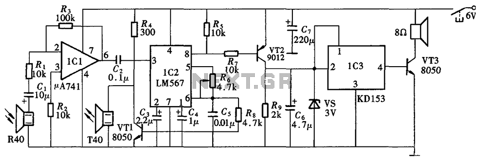
The Blind Pathfinder circuit primarily consists of the A741 operational amplifier, LM567 phase-locked loop, KD153 transistor, 8050 transistor, 9012 transistor, and various other components. The Blind Pathfinder circuit is designed to assist in navigation and obstacle detection, typically utilized in...

A circuit breaker is an automatically operated electrical switch designed to protect an electrical circuit from damage caused by overload or short circuit. Its basic function is to detect a fault condition and, by interrupting continuity, immediately discontinue electrical...
This circuit is a diagram of a mini amplifier. The amplifier circuit has a power output of 10 watts and is well-suited for car audio applications. It utilizes the TDA2009A integrated circuit as the power amplifier. To prevent excessive...