
Blind Pathfinder circuit diagram

The Blind Pathfinder circuit is designed to assist in navigation and obstacle detection, typically utilized in robotic applications. The A741 operational amplifier serves as a key component for signal amplification, allowing for the processing of weak signals received from sensors. The LM567 phase-locked loop is employed for frequency detection, enabling the circuit to determine the presence of specific signals related to navigation.
Transistors such as the KD153, 8050, and 9012 are integrated into the circuit for switching and amplification purposes. The KD153, being a general-purpose NPN transistor, can handle moderate power levels, making it suitable for driving loads within the circuit. The 8050 and 9012 transistors are utilized for their switching capabilities, allowing the circuit to control various outputs based on the processed sensor signals.
Additional components may include resistors, capacitors, and diodes, which are essential for biasing, filtering, and protecting the circuit. Proper configuration of these components is crucial for ensuring the stability and performance of the Blind Pathfinder circuit.
In summary, the Blind Pathfinder circuit integrates various electronic components to facilitate effective navigation and obstacle avoidance, making it an essential tool in the field of robotics and automated systems. Blind Pathfinder circuit is mainly composed of A741, LM567, KD153, 8050, 9012 and other components.
Related Circuits

Fire alarm circuit using an LDR (Light Dependent Resistor) as a flame sensor. It warns the user about fire accidents by detecting smoke produced during a fire. As smoke passes between an LED and an LDR, the amount of...

KA2211 is a dual audio power amplifier intended for consumer applications. It is designed to deliver high power with low dissipation and low noise. Additionally, it includes various protective features and is suitable for high-performance car audio applications. The KA2211...
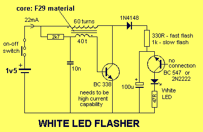
This circuit is very similar to a Joule Thief, but it utilizes two transistors, does not include a transformer core, and employs only one inductor. The described circuit operates on principles akin to those of a Joule Thief, which is...
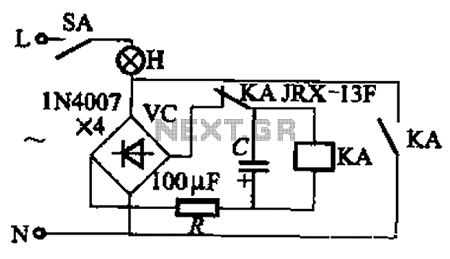
The circuit illustrated in Figure 13-3 consists of two configurations: (a) a DC power supply and (b) an AC power supply. Both configurations are utilized to control a relay. The flash frequency of the relay is determined by the...

This is a booster antenna circuit designed for frequencies ranging from 550 kHz to 1650 kHz, aimed at amplifying signals received from a telescopic antenna. It covers the medium waveband within this frequency range. To drive low impedance (50...
R1, D3, and C1 are optional components. Only one LED is necessary. If the LED does not illuminate, try reversing its polarity. Initially, a single 555 circuit was used, but high current consumption was a concern. Additionally, the R5...