
SensorCircuit Of Lie Detector

The Lie Detector Circuit operates on the principle of measuring physiological responses, typically galvanic skin response (GSR), to determine truthfulness. The circuit is designed to detect minute changes in skin conductivity, which can vary with emotional states.
Key components include a high-impedance operational amplifier, which amplifies the small variations in skin resistance. A capacitor is strategically placed in the circuit to filter out 50Hz noise commonly introduced by AC mains, ensuring that the readings are accurate and not influenced by external electromagnetic interference.
The circuit typically includes a voltage divider configuration that allows for the measurement of skin resistance. When a subject experiences stress or anxiety, their skin resistance decreases, leading to a measurable change in the output voltage of the operational amplifier.
Additional components may include a microcontroller for data logging and analysis, as well as visual indicators such as LEDs to provide immediate feedback on the subject's physiological state. The output can be further processed to produce a more comprehensive analysis of the subject's responses, enhancing the overall effectiveness of the lie detection process.
Overall, the Lie Detector Circuit is a sophisticated assembly of electronic components that work together to provide insights into human emotional responses, making it a valuable tool in various applications, including psychological research and security screenings.The following circuit shows about Lie Detector Circuit Diagram. Features: capacitor and removes the 50Hz induced mains hum that is found on a .. 🔗 External reference
Related Circuits
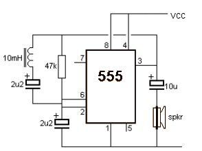
This metal detector electronic project schematic circuit is designed using a simple 555 timer integrated circuit. The schematic circuit requires few external electronic components. The metal detector circuit utilizes the 555 timer IC in an astable mode configuration, which generates...
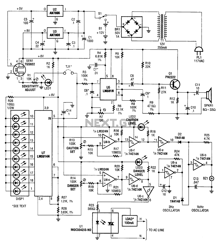
A gas sensor (from Allegro Electronics, Cornwall Bridge, CT06754 Ts GS823) activates in the presence of explosive gas. U5 functions as a voltage-to-frequency converter, with the sensor producing a frequency that is proportional to conductance. The output frequency varies...
Processor-based systems typically require a voltage supervisor chip to generate a clean reset pulse for the processor whenever a brown-out condition in the power supply is detected. More complex designs that utilize multiple power supplies can become unreliable if...
A PIC microcontroller and an LCD have been integrated into a basic radiation detector, enabling the display of total counts over a 24-hour period or counts per second, as well as the relative gamma strike energy level. The energy...
This electronic lie detector circuit project will provide two readings: one for challenging questions posed to the subject and another to indicate their emotional state. The electronic lie detector circuit operates on the principles of galvanic skin response (GSR) and...
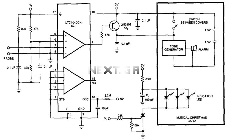
This circuit was originally designed to detect low water levels in a Christmas tree stand, but it can also be utilized as a water-level detector for pump controls and water sensors in garden and lawn applications. It employs a...