
sequential timer circuit diagram using 22

The NE555 timer IC is a versatile component widely adopted in electronic circuits for timing applications. It can operate in three modes: astable, monostable, and bistable. In the astable mode, the NE555 generates a continuous square wave output, while in monostable mode, it produces a single pulse when triggered. The bistable mode allows the circuit to maintain its state until it receives a trigger signal to change states.
In a sequential timer circuit, the NE555 can be configured in monostable mode to create a series of timed outputs. Each output can be connected to a subsequent stage of the circuit, allowing for precise control over the timing of each event in the sequence. By adjusting the resistor and capacitor values in the timing circuit, the duration of each output pulse can be finely tuned to meet specific application requirements.
The flexibility of this circuit allows it to be employed in a range of systems, from simple test equipment to more complex automation processes. The ability to use modulation techniques enables designers to create varying waveform outputs, further enhancing the circuit's functionality. The NE555 datasheet provides comprehensive specifications and application notes, which are essential for understanding the full capabilities of this IC in sequential timer applications.
In summary, the sequential timer circuit utilizing the NE555 timer IC is an invaluable tool in electronic design, providing reliable timing control for a multitude of applications. Its adaptability and precision make it a preferred choice for engineers and designers seeking to implement sequential control in their projects.A sequential timer circuit device are used in many applications for initializing conditions during start-up or for activation of test signals in sequences such in test equipment device. The circuit diagram below shows a sequencer circuit with possible applications in many sistems. As you can see, it uses the NE555 precision timer IC which capable of producing accurate time delays or oscillation. These timing circuits can be connected to provide such sequential control with various combinations of astable or monostable circuit connections. You can used it with or without modulation for extremely flexible waveform control. You may see the NE555 Datasheet here (source: ) 🔗 External reference
Related Circuits
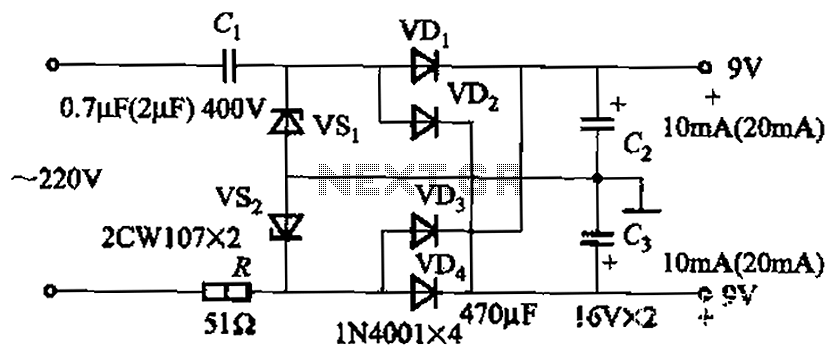
The circuit's output current capacity is influenced by the bulk capacitor Cl. When the capacitance of Cl is changed from 0.7 µF to 2 pF, the output current can be increased from approximately 10 mA to around 20 mA,...
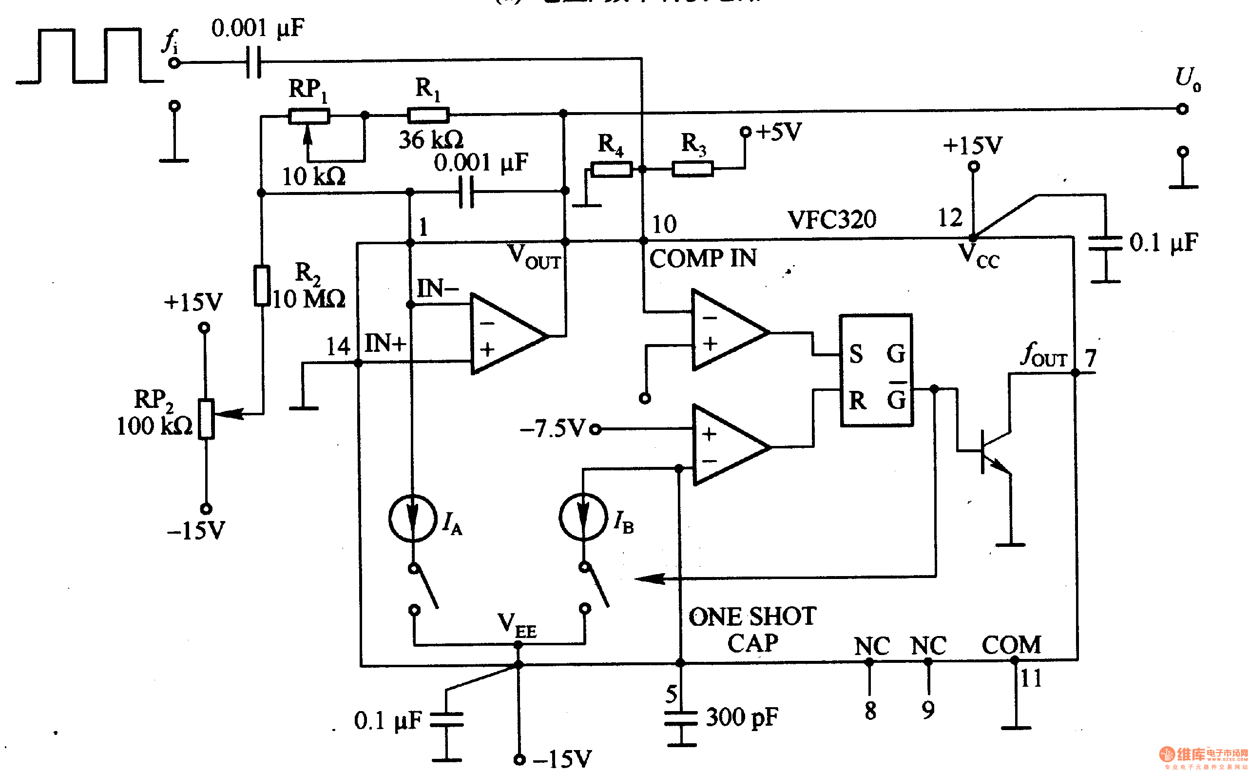
Figure 1-22 (a) illustrates a circuit that converts an input voltage of 0 to +10V (Ui) into a pulse with an output frequency ranging from 0 to 100kHz. In this configuration, pin 7 of the VFC320 is connected to...
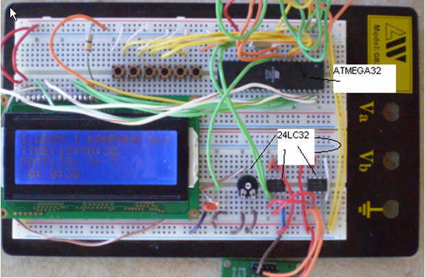
This circuit is a church bell controller. Basic component is an ATmega32 microcontroller. At the circuit 2 24LC32 EEPROM memories is being used, the 1st for internal standard melodies and the 2nd one is for user's compositions. This feature...
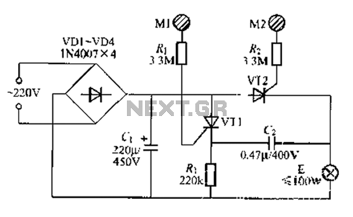
A circuit configuration features a relatively new strong key touch-state switch. Normally, the thyristors VT1 and VT2 are in the off-state, allowing minimal current to pass through the lamp F. At this point, the capacitance C comes into play....
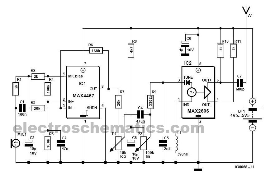
This simple FM wireless microphone transmitter can transmit speech over a short range. It can be used as a simple cordless microphone. The circuit uses two. The FM wireless microphone transmitter is designed for short-range audio transmission, making it suitable...
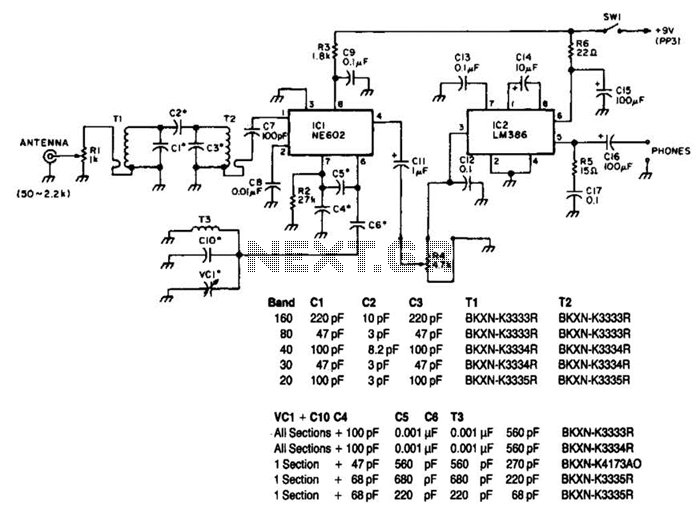
Note that T1 and T2 are TOKO components, including part numbers for the coils T1 and T2. The direct-conversion receiver shown utilizes a double-tuned input network made from readily available TOKO coils. IC1, an NE602, serves as a voltage-controlled...