
Sequential timing

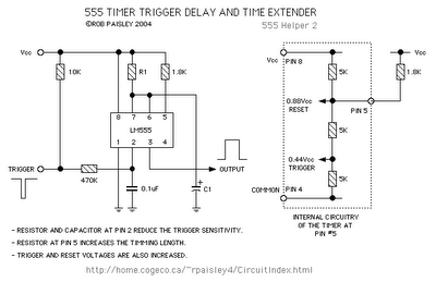
The described circuit employs a dual timer IC, such as the 555 timer, configured in a monostable mode for both halves. The first half of the timer generates a pulse when triggered, which is determined by the resistor R1 and capacitor C1 values. The output pulse width (t1) is calculated using the formula t1 = 1.1 * R1 * C1. This output is then fed to the second half of the timer through a 0.1 µF coupling capacitor, which allows only the changing voltage to pass while blocking any DC component.
When the output pulse from the first timer ends, it triggers the second timer, which has its timing set by resistor R2 and capacitor C2. The duration of the second timing cycle (t2) can be calculated using the formula t2 = 1.1 * R2 * C2. The entire configuration allows for precise control over two sequential timing intervals, which can be useful in applications such as LED blinking circuits, delay timers, or sequential activation of devices.
The use of a coupling capacitor ensures that the output from the first timer does not interfere with the DC levels of the second timer, maintaining the integrity of the timing intervals. Proper selection of resistor and capacitor values is crucial to achieve the desired timing characteristics, and the circuit can be fine-tuned by adjusting these components. The design is versatile and can be adapted for various applications requiring sequential timing functions.By utilizing both halves of the dual timer it is possible to obtain sequential timing. By connecting the output of the first half to the input of the second half via a 01 µ-F coupling capacitor, sequential timing may be obtained. Delay ti is determined by the first half and h by the second half delay. The first half of the timer is started by momentarily connecting pin 6 to ground When it is timed out (determined by 1R1C1) the second half begins. Its time duration is determined by 1R2C2.
Related Circuits
The following circuit illustrates a Set Timing Calculator Circuit. This circuit is based on the LM555 integrated circuit. Features include the provision of a delay of approximately... The Set Timing Calculator Circuit utilizing the LM555 integrated circuit (IC) is designed...
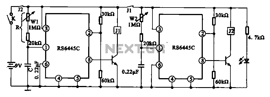
The timing integrated circuit (IC) RS6445C functions as a blocking oscillator. It features two segments, WI and W2, which are utilized to adjust the working time and the closure time. These adjustments can be continuously set within a range...
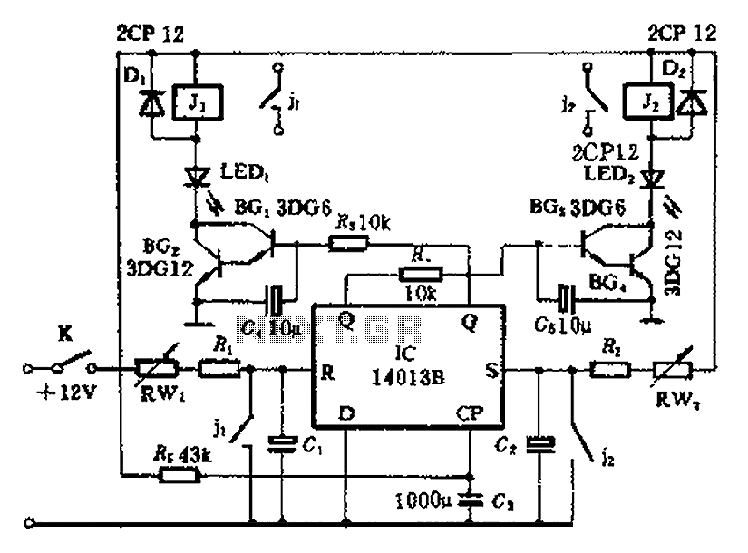
The timing control circuit is a sequential circuit that allows for sequential timed control of two switches. The control time can be adjusted from a few seconds to several tens of seconds. If mechanical control is applied for reciprocating...
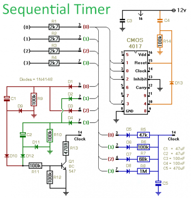
This timer is designed to generate a sequence of up to ten distinct events. Each event's duration can be set independently, and the sequence can be configured to run a predetermined number of times or continuously. Additionally, the individual...
This simple electronics timing light uses an RC circuit as a delay-off timer to control an incandescent lamp via a relay. The described timing light circuit employs a resistor-capacitor (RC) network to create a time delay that governs the operation...
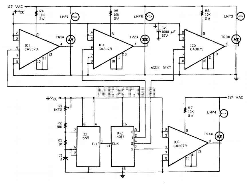
A 555 timer, referred to as IC1, controls a 4017 CMOS decade counter. The first four outputs of the 4017 drive a CA3079 zero-voltage switch. Pin 9 of the CA3079 is utilized to inhibit output from pin 4, which...