
Set Timing Calculator With The LM555IC

The Set Timing Calculator Circuit utilizing the LM555 integrated circuit (IC) is designed to generate precise time delays based on external component values. The LM555 is a versatile timer IC that can be configured in various modes, including monostable and astable operation. In the monostable configuration, the circuit generates a single output pulse of a specific duration upon receiving a trigger signal.
In this circuit, the timing interval is determined by the resistor (R) and capacitor (C) values connected to the LM555. The time delay (T) can be calculated using the formula:
T = 1.1 × R × C
Where:
- T is the time delay in seconds,
- R is the resistance in ohms,
- C is the capacitance in farads.
The components selected for R and C will dictate the length of the delay. For example, if a resistor of 100 kΩ and a capacitor of 10 µF are used, the calculated delay would be approximately 1.1 seconds.
The circuit typically includes a trigger input that activates the timing sequence. When a low voltage signal is applied to this input, the output of the LM555 goes high, and the timing cycle begins. After the designated time interval, the output returns to its low state. This behavior makes the circuit suitable for applications such as timers, pulse generators, and delay circuits in various electronic projects.
Additional components may include diodes for protection against reverse polarity and capacitors for noise filtering to ensure stable operation. The circuit can be powered using a standard DC voltage supply, typically ranging from 5V to 15V, depending on the specific requirements of the application. Proper layout and connection of components are crucial for optimal performance and reliability of the timing calculator circuit.The following circuit shows about Set Timing Calculator Circuit. This Circuit based on the LM555IC. Features: provide a delay of approximately .. 🔗 External reference
Related Circuits
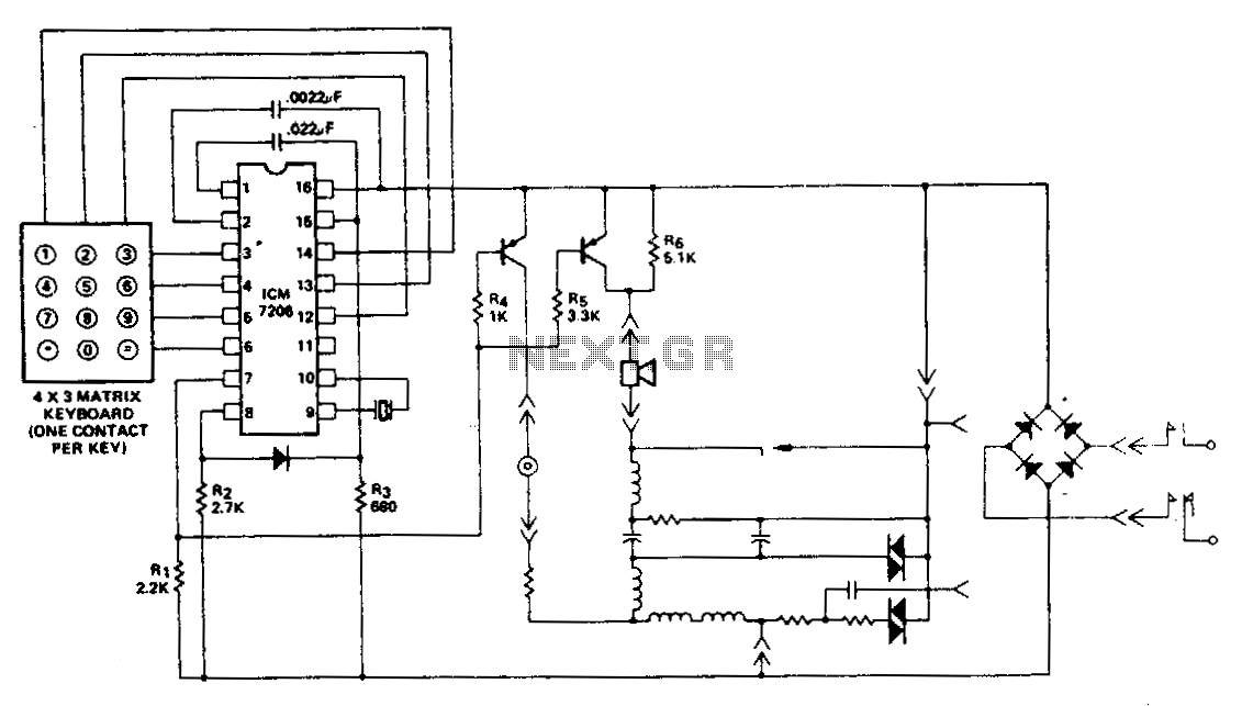
This encoder utilizes a single contact per key keyboard and manages all other switching functions electronically. A diode connected between terminals 8 and 15 limits the output to no more than 1 V negative concerning the negative supply, Vss....
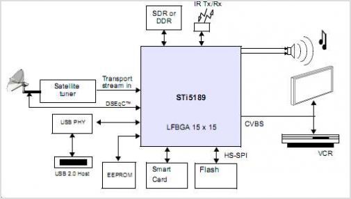
The STI5211 is a standard definition, full back-end processor designed for satellite set-top boxes, adhering to ATSC, SMPTE VC-1, DVB-S2, DIRECTV, DCII, and ARIB BS4 specifications. It delivers high performance for low-cost standard definition systems. Compared to the STi5202,...
This timer circuit is similar to the 5 to 30 minute timer, but when switch S1 is closed, the on/off action of the circuit continues indefinitely until S1 is opened again. A 7555 timer and a low leakage capacitor...
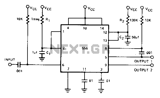
By utilizing both halves of the dual timer, sequential timing can be achieved. The output of the first half is connected to the input of the second half through a 0.1 µF coupling capacitor, enabling this sequential timing. The...
U20 is a 556 timer configured as a one-shot multivibrator. The output pulse width is determined by the values of R34 and C24, calculated as Pulse width = 1.1 x R34 x C24, resulting in a duration of 0.5...
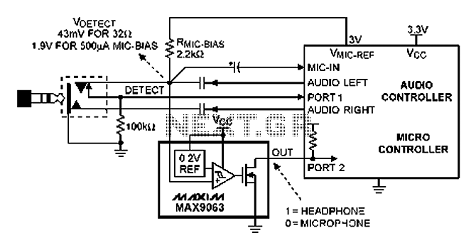
A headphone type detection circuit is illustrated in the attached figure. The 2.2k RMIC-BIAS resistor connected to the audio controller provides a low-noise reference voltage (VMIC-REF). When the audio jack is inserted, the VMIC-REF voltage through RMIC-BIAS is applied...