
Analog Timing Light Project

The described timing light circuit employs a resistor-capacitor (RC) network to create a time delay that governs the operation of an incandescent lamp. The fundamental operation relies on charging and discharging the capacitor through the resistor, which determines the time interval before the relay deactivates the lamp.
In this circuit, the capacitor is charged through the resistor when power is supplied. The time constant, defined as the product of the resistance (R) and capacitance (C) values (τ = R × C), dictates how long the capacitor takes to charge to a specific voltage level. Once the voltage across the capacitor reaches a predetermined threshold, typically set by the relay's control voltage, the relay is activated, allowing current to flow to the incandescent lamp.
The relay acts as an electronic switch, enabling the control of higher power loads without the need for a direct switch. When the capacitor discharges after reaching the threshold, the relay is deactivated, turning off the lamp. This mechanism ensures that the lamp remains lit for a specified duration after the triggering event, providing functionality for applications such as automotive timing lights or decorative lighting systems.
Additional components may include a diode across the relay coil to prevent back EMF from damaging other circuit elements, as well as a potentiometer to allow for adjustable timing settings. Proper selection of the resistor and capacitor values is essential to achieve the desired delay time, making this circuit versatile for various timing applications.
Overall, this simple yet effective timing light circuit demonstrates the practical use of RC timing principles in controlling incandescent lamps through relay actuation.This simple electronics timing light uses RC circuit as a delay OFF timer to control an incandescent lamp by using a relay 🔗 External reference
Related Circuits

This design circuit is for audio graphic equalizers, which are commonly found in commercial products, yet circuits for them are rarely published. The circuit features a simple design that requires an operational amplifier (op-amp) to amplify the input signal....

This optodetector measures the position of the ball by the amount of light transmitted by the infrared LED. It generates a linear signal across the small area of the detector, rather than simply providing an "on" or "off" output....
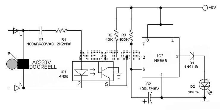
This 6V battery-operated doorbell light circuit can be connected in parallel with any existing AC 230V doorbell. When the doorbell switch is pressed, the bell sounds as usual, and the AC mains supply available across the doorbell is routed...
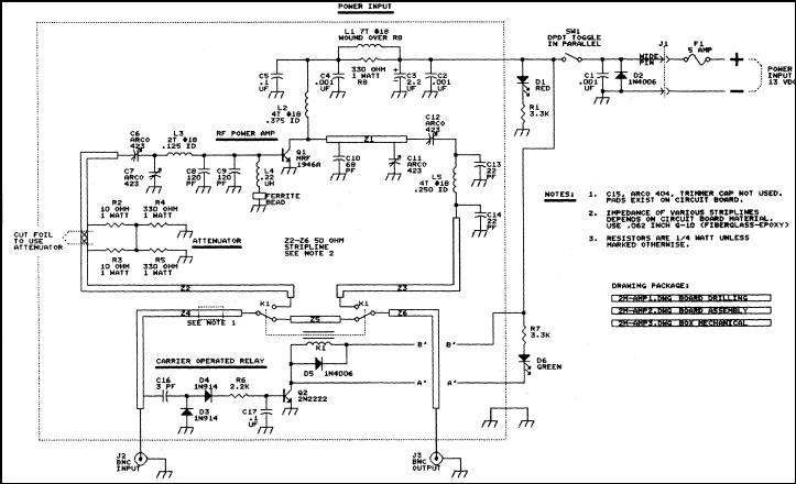
This article discusses a 2-meter amplifier capable of delivering an output of 25-30 watts. Over 35 units have been acquired at a cost of less than $50 each in bulk. Photo A displays the final version of the circuit...
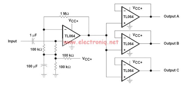
This audio distribution electronic project circuit diagram is designed using the TL064 or TL06 operational amplifiers and some other common electronic parts. The audio distribution circuit utilizes TL064 or TL06 operational amplifiers, which are quad op-amps known for their low...
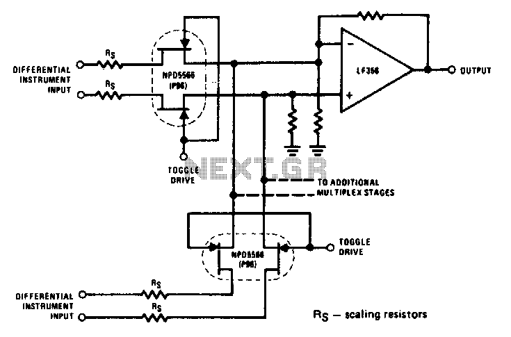
The NPD5566 monolithic dual is utilized in differential multiplex applications where the Rds(ON) should be closely matched. The monolithic dual tracks at better than ±1% over a wide temperature range of -25°C to +125°C, making it an unusual yet...