
Serial Servo Motor Controller

The servo controller described is an advanced interface designed for controlling multiple hobby servo motors through a personal computer (PC). This project builds upon previous iterations by introducing enhanced capabilities for port selection and communication speed, thereby improving user experience and flexibility.
The core functionality of this servo controller involves interfacing with the PC's serial communication ports. The system is programmed to automatically detect available COM ports, which allows users to select their desired port dynamically. This feature is particularly beneficial in environments where multiple devices may be connected to the PC, as it eliminates the need for manual configuration of the COM port.
In addition to the improved port selection, the controller also allows users to set baud rates, which are critical for ensuring reliable communication between the PC and the servo motors. The ability to adjust baud rates accommodates a variety of setups and ensures compatibility with different hardware configurations.
The controller supports up to eight hobby servo motors, providing an additional servo port beyond the standard configuration. This expanded capability allows for more complex projects, such as robotic arms or automated systems, where multiple servos must be coordinated simultaneously.
The circuit design likely includes a microcontroller that manages communication with the PC and controls the output signals to the servo motors. The microcontroller interprets commands received from the PC and generates the appropriate pulse-width modulation (PWM) signals required to control the position of each servo motor.
Power management is also a crucial aspect of the design, as hobby servos can draw significant current. The circuit should incorporate power regulation components to ensure stable operation without overloading the system. Additionally, proper isolation and protection circuits are recommended to safeguard the microcontroller and other sensitive components from voltage spikes or noise generated by the servos.
Overall, this servo controller project provides a comprehensive solution for hobbyists and engineers looking to implement servo motor control in their applications, combining ease of use with robust functionality.The first servo controller project at http://www.rentron.com/servo.htm had the com port fixed at com1. This new version will seek out the available com ports on your PC and then let you select the desired port and baud rates.
It has 1 additional servo port as well to let you control a total of 8 hobby servo motors from the PC. 🔗 External reference
Related Circuits
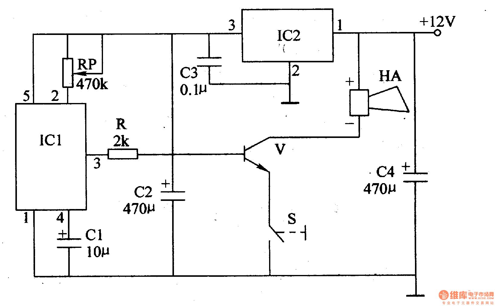
The motorcycle anti-theft alarm described in this article utilizes a proprietary displacement sensor. It is characterized by high sensitivity, good reliability, a low false alarm rate, and ease of construction. The principle of the circuit involves an integrated vibration...
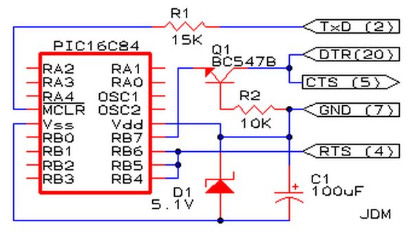
Affordable PIC Programmer. This programmer is compatible solely with the PIC16F84 microcontroller. It is reliable, as it rarely encounters errors, and functions well with nearly all computer systems, in contrast to some alternatives. The PIC programmer designed for the PIC16F84...
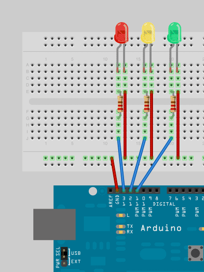
To enhance Arduino programming skills, developing a traffic light controller serves as an excellent practice project. The traffic light controller project involves designing a circuit that simulates the operation of a traffic light system, typically consisting of red, yellow, and...
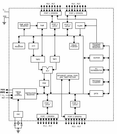
A microcontroller (MCU) is a compact computer integrated into a single circuit, comprising a relatively simple CPU along with supporting functions such as crystal oscillators, timers, sensors, and serial and analog input/output (I/O). Microcontrollers are designed for small-scale applications,...

Electric shaver motor drive circuit. It illustrates a typical motor drive circuit for an electric shaver. AC 220V is used to charge the battery through the charging circuit, which also provides power to the motor. After activating the charge-on...

Many times, code has been written for UART communication, but testing was hindered by the absence of a serial port on the laptop. A USB to serial port converter was purchased, but it did not function as expected. Frustration...