
Series-Wound Direction And Speed Motor Control
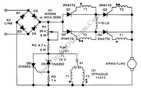
The motor controller circuit is designed to manage both the speed and direction of series-wound motors, which are commonly used in various applications due to their high starting torque and simplicity. The core component of this circuit is the silicon controlled rectifier (SCR), a semiconductor device that allows for the control of power delivery to the motor by adjusting the phase angle of the AC supply.
The operation of the circuit begins with the application of a control signal to the gate of the SCR. This signal turns the SCR on, allowing current to flow through the motor. By varying the timing of the gate signal, the effective voltage applied to the motor can be controlled, thereby regulating the motor's speed. This phase control technique is particularly effective for series-wound motors, as it takes advantage of their inherent characteristics.
Furthermore, the circuit can also be configured to reverse the direction of the motor. This is typically achieved by employing a relay or an additional set of SCRs that can switch the polarity of the voltage applied to the motor. By implementing this feature, the motor controller provides versatility for applications that require bidirectional movement.
In terms of design, the circuit may include additional components such as diodes for flyback protection, capacitors for filtering, and resistors for current limiting. A microcontroller may also be integrated to provide more sophisticated control algorithms, such as PWM (Pulse Width Modulation) for smoother speed control and enhanced efficiency.
Overall, this motor controller circuit utilizing SCRs is a robust solution for applications requiring precise control over the operation of series-wound motors, making it suitable for industrial automation, robotics, and various other fields.This is a motor controller circuit that? control the speed? and direction of series-wound Motors. This circuit employs silicon controlled rectifiers (SCR). 🔗 External reference
Related Circuits
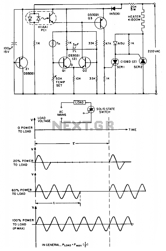
The "zero voltage switching" technique is commonly utilized to modulate heating and similar types of AC loads, where the time constant associated with the load (ranging from tens of seconds to minutes) is sufficiently long to allow smooth proportional...
Most recent cars are equipped with a significant amount of electronics, including ABS brake systems, engine control with injection calculators, airbag activation, and various comfort functions. One such function, which is often overlooked due to its commonality, is the...
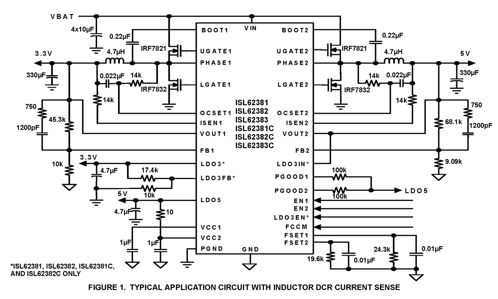
The ISL62381, ISL62382, ISL62383, ISL62381C, ISL62382C, and ISL62383C family of controllers generate supply voltages for battery-powered systems. These controllers include two pulse-width modulation (PWM) controllers, adjustable from 0.6V to 5.5V, and two linear regulators, LDO5 and LDO3, that generate...
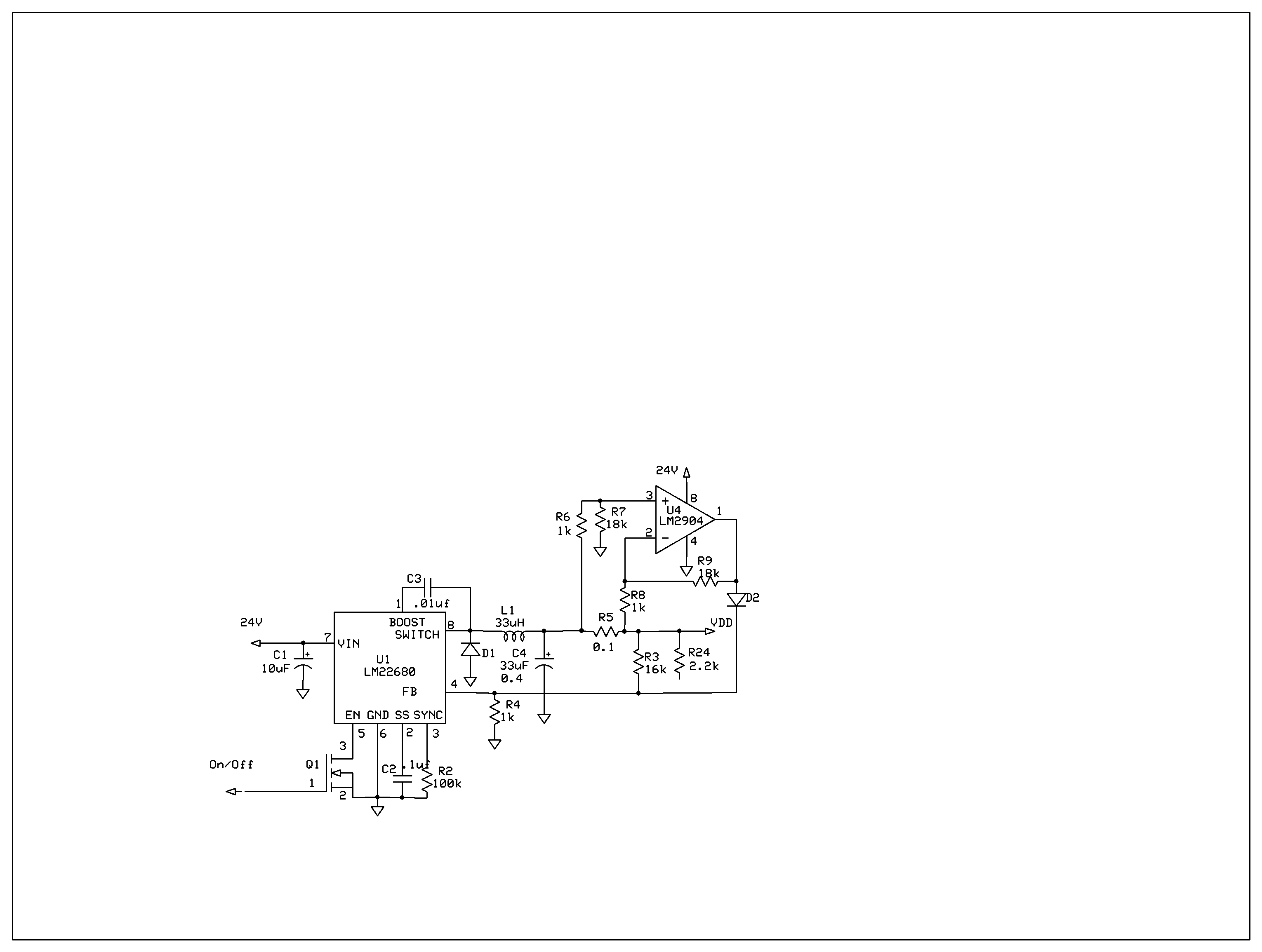
The product requires a voltage-controlled, current-limited power supply. Various switcher chips have been used with an op-amp to provide feedback for a current sense voltage to the feedback pin. Currently, an LM22680 is in use, but it has shown...
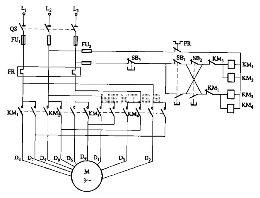
The circuit depicted in Figure 3-112 features two operation buttons: SBi, which serves as the first speed operation button, and SBz, which operates the second speed class. Both buttons facilitate two speeds in the same direction. The circuit design incorporates...
This project involves reading a thermistor using an Atmel ATtiny45 or ATMega168 microcontroller to control two fans for cooling a PC housed in a kitchen cabinet. A table is provided for converting the resistance of the BC1482 thermistor to...