
two-speed motor contactor control circuit two speeds in the same direction

The circuit design incorporates two operational buttons, SBi and SBz, that control the speed of a motor or similar device. SBi is designated for the first speed setting, while SBz is utilized for the second speed setting. Both buttons are configured to allow the device to operate at two distinct speeds in the same directional flow, enhancing versatility in applications that require varying operational speeds.
In typical implementations, SBi and SBz may be connected to a motor driver circuit that interprets the button presses and adjusts the power supplied to the motor accordingly. The circuit could utilize a microcontroller or a dedicated speed controller IC to manage the input from the buttons and modulate the output to the motor.
The first speed setting, activated by SBi, may provide a lower voltage or PWM (Pulse Width Modulation) signal to the motor, resulting in a slower rotational speed. In contrast, the second speed setting, controlled by SBz, could increase the voltage or modify the PWM duty cycle, allowing for a higher speed operation.
Additionally, protective components such as diodes may be included to prevent back EMF generated by the motor from damaging the circuit. Capacitors may also be employed to filter noise and stabilize the voltage supply, ensuring smooth operation at both speed settings.
This circuit design is applicable in various scenarios, including robotics, conveyor systems, and other automated machinery where speed control is essential for performance optimization. Circuit shown in Figure 3-112. Figure, SBi as the first speed operation button, SBz is run by the second speed class. Two speeds in the same direction.
Related Circuits
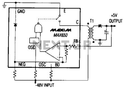
The Max650 switching regulator generates a regulated 5 V output from large negative voltages, such as the -48 V commonly found on telephone lines. This power supply requires several external components, including a transformer, and is capable of delivering...
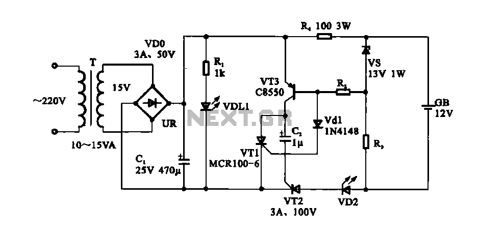
An easy automatic battery charging circuit is presented, which can automatically power off when the battery is fully charged. This design prevents overcharging. The automatic battery charging circuit operates by utilizing a voltage sensing mechanism to monitor the battery's charge...
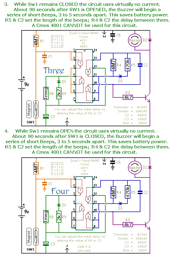
This document presents a collection of compact, self-contained alarm circuits. These circuits are designed to operate with a very low standby current, making them ideal for battery-powered applications. They can be triggered by both normally-open and normally-closed switches, while...
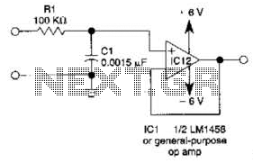
This simple filter utilizes an RC section as the filter element, incorporating a voltage follower to manage other frequencies. The -3 dB point is calculated as 1/(6.28 * RXCV), resulting in a response that drops 6 dB per octave...
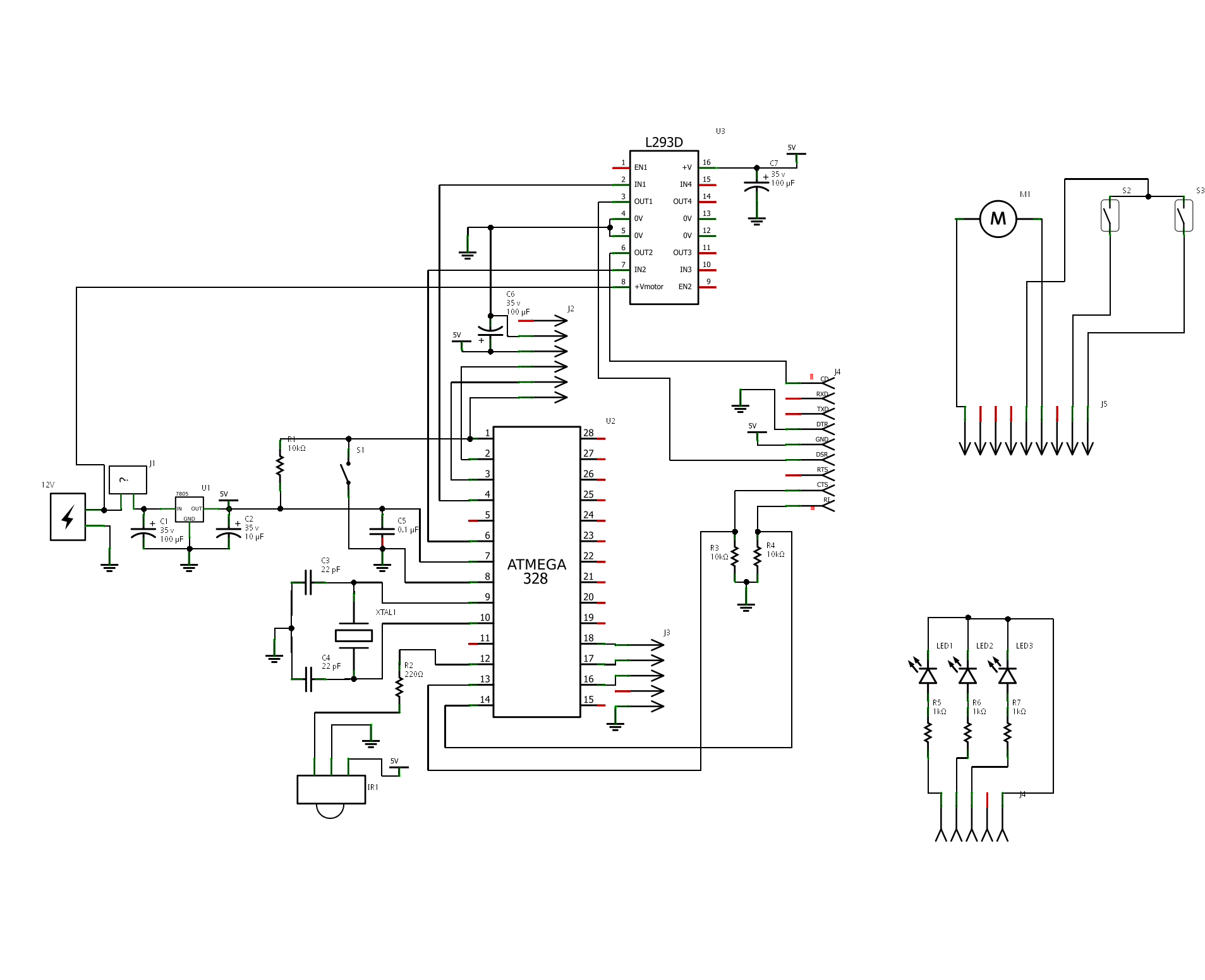
The project is "Motorized Curtain" with Remote control. It is made up of MCU ATMEGA328 with Arduino BootLoader, motor driver L293D (I used L293B with external diodes, because I couldn't find L293D), IR Receiver TSOP 1738, DC Motor from...
This is a solar tracking circuit designed to harness power from sunlight. The circuit operates optimally by maximizing sunlight exposure to generate electricity. The solar tracking circuit utilizes a combination of photovoltaic (PV) cells, sensors, and a microcontroller to adjust...