
Guitar pre-amplifier using uA 741

The preamplifier circuit is specifically tailored for high-impedance electric guitar pickups, ensuring optimal signal integrity and performance. The uA 741 operational amplifier is a versatile component known for its stability and ease of use in audio applications. In this configuration, the non-inverting amplifier setup allows for a gain greater than one, which is essential for boosting the weak signals generated by guitar pickups.
The inclusion of potentiometers R1 and R6 provides flexibility in sound shaping. R1, as a volume control, allows the user to adjust the overall output level of the preamplifier, making it suitable for various playing environments and preferences. R6, functioning as a tone control, enables the adjustment of the frequency response, allowing the guitarist to tailor the tonal characteristics to their liking.
Switch S1 introduces an additional layer of versatility by allowing the user to toggle between two distinct tonal profiles: a bright setting that emphasizes higher frequencies for a sharper, more cutting sound, and a soft setting that attenuates these frequencies for a warmer, more mellow tone. This feature can be particularly useful in live performances or recording sessions where different tonal qualities may be desired.
In designing buffer circuitry for a guitar selector gadget, the choice between op-amps and JFETs can significantly impact the tonal quality. While op-amps like the uA 741 offer greater design flexibility and ease of gain adjustment, some musicians argue that JFETs may better preserve the natural tone of the guitar. JFET circuits can provide a warmer sound, potentially making them preferable for applications where tone fidelity is paramount. If a JFET design is pursued, attention must be given to gain boosting, which can be achieved through careful selection of the JFET characteristics and circuit configuration, ensuring that the output signal remains robust and clear while retaining the instrument's inherent tonal qualities.A preamplifier circuit suitable for high impedance type electric guitar pickups is given here. The circuit is based on a uA 741 op-amp (IC1). The IC1 is wired as a non-inverting amplifier. The POT R1 can be used as a volume controller. The POT R6 can be used as tone controller. The switch S1 is used to produce brilliant or soft tonal effects. You folks who know electronics, please advise me! I am wanting to design some buffer circuitry for a homebrew fancy guitar selector gadget. I know that op-amps will give me more flexibility in circuit design over JFETs, but some people have observed that op-amp buffers sound colder and more sterile . Do you have any opinions Would a JFET circuit really preserve the guitar`s tone better If there is a difference that could be noticed, I think I`d be willing to do the more involved JFET design, though I`ll need to know how to boost the gain (I`ll want to boost the signal be a few db), which of course op-amps can do more easily.
🔗 External reference
Related Circuits
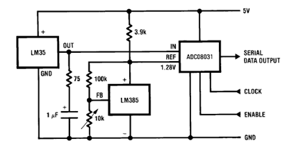
The circuit illustrates a Temperature to Digital Converter diagram utilizing the LM35 sensor, which includes a beneficial bypass capacitor connected from VIN to ground and a series RC damper. The described circuit employs the LM35 temperature sensor, a precision integrated...
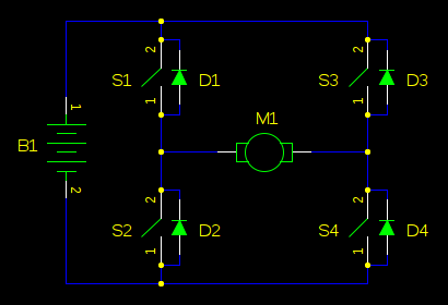
In motor control circuits, precautions must be taken to prevent the motor from feeding back into the power supply, which can cause the supply voltage to rise and potentially damage components. However, unless an external force is accelerating the...
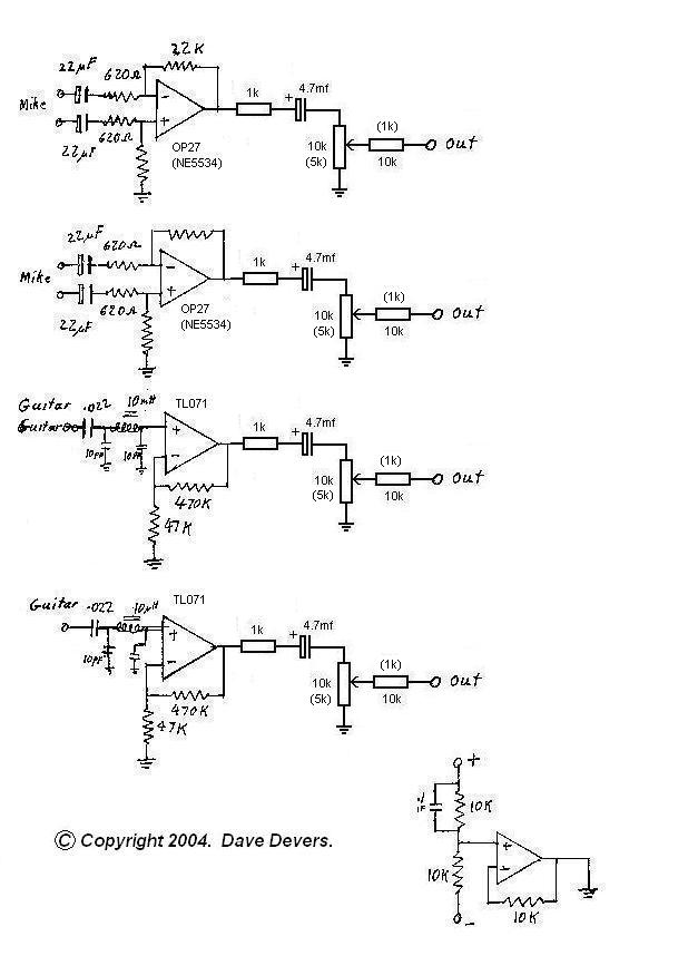
The mixer is extremely useful for direct input (DI) of guitars and basses into soundcards or other mixers, allowing for the utilization of channels on mixers that lack microphone inputs. It is particularly beneficial for one or two guitarists...
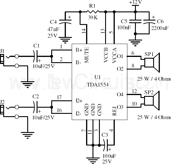
This document presents a 22-watt stereo audio power amplifier circuit diagram utilizing the TDA1554 integrated circuit from NXP Semiconductors (formerly known as PHILIPS Semiconductors). The circuit is designed to amplify stereo signals effectively. It dissipates approximately 28 watts of...
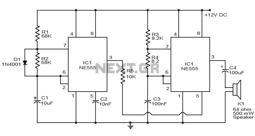
Numerous electronic circuits utilizing the NE555 timer IC have been published, and this is yet another example. The circuit diagram presented illustrates a police siren based on the NE555 timer IC. It employs two NE555 timer ICs, each configured...
This text provides information about an initial attempt at creating a circuit, referencing a schematic found in an application note for a specific module. However, it notes that the schematic did not include details for the power supply circuitry,...