
Servo Controller Help

To address the issue of limited servo motion, it is essential to analyze the circuit design and parameters influencing the servo's operation. Servos typically require a control signal that varies between 1 ms to 2 ms pulse width for a full range of motion from 0 degrees to 180 degrees. If the circuit is only producing a pulse width corresponding to a 90-degree rotation, several factors may be at play.
First, verify the power supply to the servo. Servos usually operate at a specific voltage range, commonly 4.8V to 6V. Insufficient voltage can restrict the servo's range of motion. Ensure that the power supply can deliver adequate current as well, as servos may draw more current under load.
Next, inspect the pulse width modulation (PWM) signal being sent to the servo. The PWM signal should be generated by a microcontroller or a dedicated servo controller. Check the programming or configuration of the controller to ensure that it is set to produce the correct PWM frequencies and pulse widths. For example, a standard servo requires a frequency of approximately 50 Hz.
Additionally, examine the connections and components within the circuit. Loose connections, inadequate resistors, or faulty components can also impede the proper functioning of the servo. It is advisable to use an oscilloscope to visualize the PWM signal and ensure it meets the servo's specifications.
Lastly, consider the servo's mechanical constraints. If the servo is physically blocked or if the linkage system is not designed for full range motion, it may only rotate 90 degrees regardless of the input signal. Ensure that the mechanical setup allows for the desired range of motion without obstruction.
By systematically evaluating these aspects, it should be possible to diagnose and resolve the limitations in the servo's range of motion.I`m not able to get this circuit to give me full range of motion of a servo (only about 90 degrees). Maybe someone can take a look at the circuit and.. 🔗 External reference
Related Circuits

Voltage regulator ICs (78xx series) provide a steady output voltage, in contrast to a widely fluctuating input supply, when the common terminal is grounded. The 78xx series of voltage regulator integrated circuits (ICs) are widely utilized in electronic circuits to...
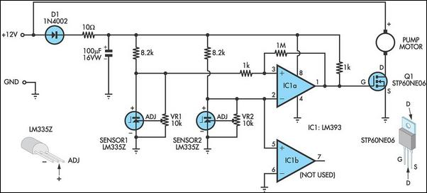
This circuit optimizes the operation of a solar hot water system. When the water in the solar collector is hotter than the storage tank, the pump runs. The circuit comprises two LM335Z temperature sensors, a comparator, and a MOSFET....
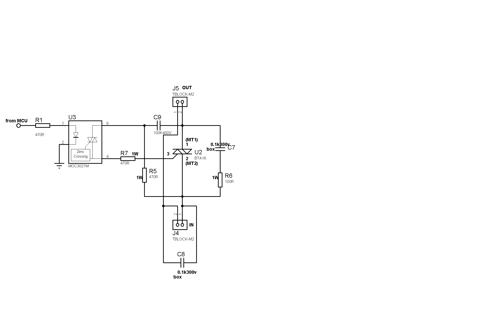
Sufficient snubbering appears to be present around the TRIAC, which should mitigate DV/DT-based switching, preventing the TRIAC from inadvertently turning on due to noise on the gate lead. The issue likely resides on the microcontroller side. When the microcontroller...
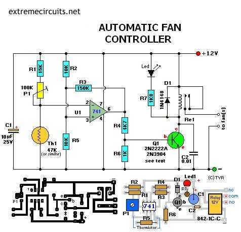
Transistor Q1 can be a 2N2222(A), 2N3904, NTE123A, ECG123A, etc. Not critical at all. It acts only as a switch for the relay so almost any type will work, as long as it can provide the current needed to...
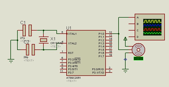
A program is available to control a simple servo motor in both directions. This program has been tested and can be shared for others to benefit from it. It allows the servo motor to rotate in both clockwise and...
The controller is a prototype and works well in my plane with 7 cells and a Graupner-Speed 600. The described controller is a prototype designed for use in a model aircraft, specifically optimized to operate with a battery pack consisting...