
speedcontroller TRIAC switching problem

The circuit in question involves the use of a TRIAC for switching applications, typically in AC loads. The presence of snubbering components is essential to protect the TRIAC from voltage transients that could cause unintended triggering. The microcontroller plays a crucial role in controlling the TRIAC through an optocoupler, which provides electrical isolation between the high-voltage AC side and the low-voltage control side.
In this configuration, the optocoupler is utilized to isolate the microcontroller from the AC load. The redesign of the microcontroller circuit is necessary to ensure that the optocoupler operates reliably. The optocoupler's LED should be connected such that it receives a clear HIGH signal when the microcontroller intends to turn on the TRIAC. By connecting the anode of the optocoupler LED to the positive voltage supply and the cathode to the microcontroller pin via resistor R1, the microcontroller can actively control the LED state.
The choice of R1 is critical; it should be selected to limit the current to the optocoupler's LED within its specified range while ensuring that a sufficient voltage drop occurs across it when the microcontroller pin is LOW. This design modification eliminates the risk of the LED being partially illuminated due to weak pull-up currents during the reset state of the microcontroller.
Additionally, the incorporation of an external pull-up resistor on the microcontroller pin is advisable for enhanced reliability in maintaining the optocoupler in an OFF state when not actively driven LOW. This measure is particularly important when dealing with line voltages, where unintended triggering could pose safety hazards.
Finally, analyzing the specifications of the TRIAC is essential, especially if it is classified as a sensitive-gate TRIAC. In environments with significant electrical noise, the characteristics of the TRIAC may necessitate further protective measures, such as improved snubbering circuits, to ensure stable operation without false triggering. The overall design should prioritize both functionality and safety in controlling AC loads through microcontroller interfacing.You already appear to have sufficient snubberring around the TRIAC which should eliminate DV/DT based switching (the TRIAC turning itself on due to noise on the gate lead) which I believe that your issue is on the micro side of things. I think your issue is as follows. When the micro is in reset, all of its pins are inputs. This isn`t quite the same thing as having the left side of R1 disconnected since the micro also probably has internal pullups. These pullups are too weak to drive the opto LED strongly, but I bet if you put a meter across R1 you will see maybe a few dozen to a hundred microvolts.
That might be enough to trigger that opto. I would rework the micro side of your circuit so that the anode of the optocoupler LED goes to +V and the cathode goes to your micro through R1; your micro will then have to drive the output LOW to turn on the TRIAC, but it will eliminate that brief moment where the micro comes out of reset and the pin is an input and drives the LED weakly. I would also add an external pull-up resistor just because you`re working with line voltage and I like the assurance of a stronger pull-up resistor to make sure the opto stays off.
I would also investigate the larger TRIAC to see what exactly its switching characteristics are. If it`s a sensitive-gate TRIAC and you have a noisy environment you may need to take a closer look at your snubberring. 🔗 External reference
Related Circuits

The circuit consists of two separate 3023 optoisolators controlling two distinct triacs, each responsible for powering a large 3-phase contactor. One contactor operates correctly, while the other experiences issues, not receiving sufficient power to engage fully. The upper image...
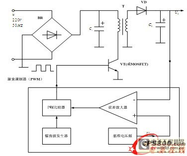
The energy conservation provided by switching power supplies has garnered significant attention due to its substantial economic benefits, leading to rapid adoption across various sectors. With the swift advancement in power technology, high-frequency operation has become a prevailing trend...
This circuit can be used to charge accumulator and cell batteries. It features a very stable output that extends the battery life and maximizes the added battery capacity. The charging process is also quite fast, optimizing the time required...
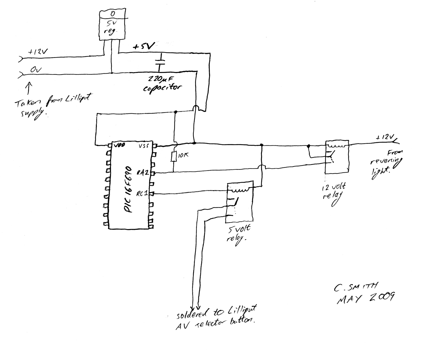
There have been numerous discussions regarding the Lilliput's inability to automatically switch, despite the presence of this feature in the secret menu. The Lilliput display is a versatile device often used in various applications, including professional video production and...
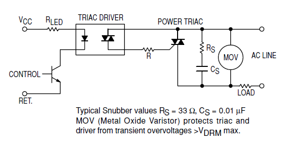
Interfacing the BT139-600 TRIAC with the MOC3051-M Opto-triac requires the construction of a snubber circuit as illustrated in the MOC3051M opto-triac's datasheet on page 8, figure 12. The load connected to this circuit will be a 230V AC, 4A...
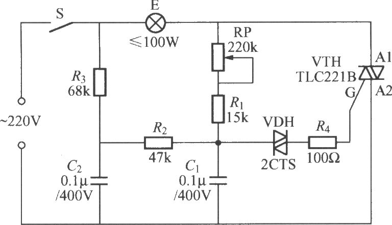
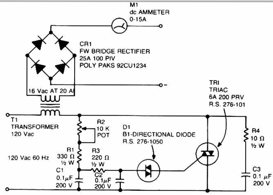
To address the lag and light transition issues, a Triac dimming light circuit featuring a dual time constant can be employed. This circuit enhances the resistor-capacitor network formed by R3 and C2. The reduced charge on capacitor C1 can...