
servo light dimmer

The dimmer circuit operates by controlling the phase angle of the AC voltage supplied to the load, allowing for smooth dimming capabilities. The triac serves as the primary switching device, enabling the circuit to handle high power loads without overheating. When the circuit is powered, VR1 adjusts the gate trigger of the triac, thereby controlling the amount of voltage delivered to the load.
Resistors R2 and R3 are crucial for setting the reference voltage and current through the control circuit, which influences the minimum brightness level. The capacitor C1 works in conjunction with these resistors to filter and stabilize the voltage, ensuring a consistent performance across varying load conditions.
This dimmer is suitable for a wide range of applications, from residential lighting to commercial settings, where precise control over illumination is required. The ability to handle loads greater than 1600 watts makes it particularly advantageous for use with high-wattage lighting fixtures. Additionally, the adjustable minimum brightness feature allows for customized lighting environments, enhancing both functionality and user experience.
Overall, this dimmer circuit represents a robust solution for effective illumination control, combining high power capacity with versatile adjustment features.And this is exactly what this dimmer does. One plus point is that it has a power handling capacity exceeding 1600 watts, far exceeding the ordinary 300 watt types. Any type of 400 PIV, 8 ampere triac may be used in the circuit VR1 provides illumination control. R2, R3 and C1 set the minimum brightness level which can however be altered. 🔗 External reference
Related Circuits
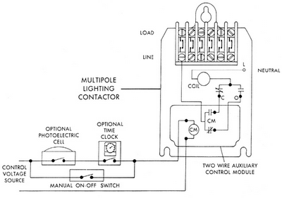
Sensors for lighting controls include photoelectric sensors and presence detectors. Photoelectric sensors typically switch lighting on at dusk and off at dawn, with adjustable settings for sensitivity to light levels. They feature built-in time delays to prevent unwanted switching...
The wireless light switch circuit described here requires no physical contact for operating the appliance. You just need to move your hand between the infrared LED (IR LED1) and the phototransistor (T1). The infrared rays transmitted by IR LED1...
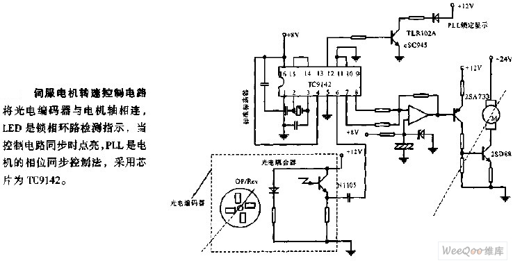
The servo motor speed control circuit connects the photoelectric encoder to the motor shaft. The LED serves as an indicator light for the phase-locked loop (PLL) detection, illuminating when the control circuit is synchronized. The PLL employs a phase...
Here is a schematic of a rechargeable 9-LED flashlight using two Gates SLA cells and nine LEDs. It is as bright as when the single bulb was used, and lasts 3 times longer per charge. That is about 10...
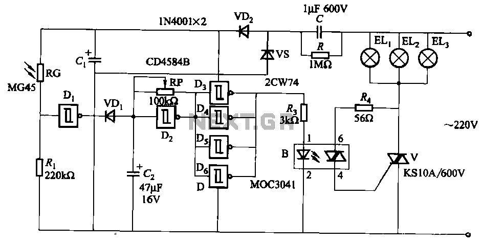
The circuit utilizes a CD4584B six Schmitt trigger integrated circuit (IC) with components Di and Ri forming a photometric circuit. D2, along with RP and C2, comprises an adjustable frequency ultra-low frequency oscillation device, where RP serves as an...
When the lights of an oncoming car are detected by the photo-transistor Q1, the circuit activates. Sensitivity is adjusted by the 22-megohm resistor, R5, to approximately half a foot-candle. The relay employed has a 12-volt, 0.3A coil. The L14C1...