
Servo motor speed control circuit

The servo motor speed control circuit is designed to regulate the speed of a servo motor by implementing a feedback mechanism that utilizes a photoelectric encoder. This encoder is mechanically linked to the motor shaft, providing real-time position and speed data to the control system. The integration of the encoder allows for precise control of motor speed, ensuring that the motor operates at the desired setpoint.
The phase-locked loop (PLL) is a critical component of this circuit, serving to synchronize the motor's operation with the input signal. The TC9142 chip is utilized for its capabilities in phase detection and control. This chip processes the feedback from the encoder, comparing the actual motor speed to the desired speed. If a discrepancy is detected, the PLL adjusts the control signals sent to the motor, thereby achieving synchronization.
The LED indicator plays an essential role in providing visual feedback regarding the status of the PLL. When the control circuit achieves synchronization, the LED illuminates, signaling that the motor is operating correctly within its designated parameters. Conversely, if the LED is off, it may indicate a loss of synchronization, prompting further investigation into the system's performance.
In summary, this servo motor speed control circuit combines the functionalities of a photoelectric encoder, a PLL for phase synchronization, and an LED indicator to create an efficient and effective motor control solution. The use of the TC9142 chip enhances the circuit's ability to maintain precise control over motor speed and performance, making it suitable for various applications in automation and robotics.The servo motor speed control circuit connects the photoelectric encoder with the motor shaft, the LED is the indicator light of the PLL detection, it turns on when the control circuit is synchronous. The PLL is the phase synchronous control method of the electrical moter, it uses the chip of TC9142..
🔗 External reference
Related Circuits

The adjustment control for the contrast of an LC-Display is typically a 10-k potentiometer. This functions effectively as long as the power supply voltage remains constant. However, in scenarios where the power supply voltage fluctuates, such as with battery-operated...
This oscillator is a variation of the oscillator presented by Ulrich L. Rohde, DJ2LR, in his article "Evaluating Noise Sideband Performance in Oscillators," published in Ham Radio, October 1978, Page 51. The original circuit can be found at the...
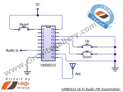
This article provides the circuit schematics for an FM transmitter along with the necessary explanations. The primary component utilized is the VMR6512 IC, a highly integrated FM audio signal transmitter chip designed for Hi-Fi audio applications. This chip can...
Switch S2 is used for increasing and switch S3 is used for decreasing the volume. Similarly, switches S4 and S5 are provided for second channel (right channel) volume control. Also, pin 14 of IC2 can be connected to IC...
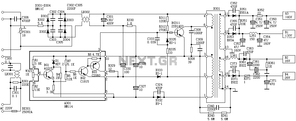
Oscillation: The positive terminal voltage of C310 is approximately 300V. The resistors R311 and R312 are connected to the switch BG311 at the B pole, while the B301 winding via the switching transformer (4) and (6) is connected to...
This project is a digital Automatic Gain Control (AGC) system using a PIC16F876 MCU. The ability to set the gain level in a circuit and have it control itself is a very useful function. This circuit is a building...