
Three light control road construction warning light circuit

The circuit design centers around the CD4584B, which contains six independent Schmitt trigger circuits. These circuits are characterized by their ability to provide clean digital signals from noisy inputs, making them ideal for applications requiring precise signal processing. The photometric circuit, formed by components Di and Ri, is responsible for detecting light levels and converting them into an electrical signal that can be processed by the Schmitt trigger.
The adjustable frequency oscillation device consists of D2, RP, and C2. Here, RP acts as a variable resistor, enabling the adjustment of the oscillation frequency. The capacitor C2 works in conjunction with the resistor to determine the timing characteristics of the oscillation, allowing for a wide range of ultra-low frequency outputs. This feature is particularly useful in applications such as blinking LED indicators or low-frequency sound generation.
D3 through D6 are connected in parallel to serve as an output controller, which effectively manages the output signal generated by the oscillation device. This configuration ensures that the output can drive a load with sufficient current, providing flexibility in controlling various electronic devices.
The inclusion of an opto-coupler B in the circuit design serves to isolate different sections of the circuit, enhancing safety and preventing interference between components. The opto-coupler allows for the control of a Triac, which is a type of semiconductor device used for switching and controlling power in AC circuits. By using the opto-coupler to trigger the Triac, the circuit can effectively manage larger loads while maintaining the integrity of the control signals.
Overall, the design allows for dynamic control of blinking frequencies through the adjustment of RP, making it suitable for a variety of applications in lighting and signal processing. The combination of Schmitt triggers, adjustable oscillators, and opto-isolation provides a robust framework for developing reliable electronic circuits.It uses CD4584B six Schmitt trigger IC (Di ~ Ds). Wherein Di and Ri, RG composition photometric circuit, D2 and RP, C2 composed of adjustable frequency (adjustment potentiometer RP) ultra-low frequency oscillation device, D3 ~ D6 in parallel as output controller. Opto-coupler B control Triac V work. Regulator RP, can change the blinking frequency.
Related Circuits
Tubular xenon lamp power, high brightness, known as the "little sun." Tubular xenon lamp wiring is illustrated in Figure 2-6. The tubular xenon lamp is a high-intensity discharge (HID) light source, characterized by its ability to produce a bright white...

The circuit depicted in Figure 3-69 is designed for applications requiring frequent timing control for motor reversing operations. In this configuration, thyristors V1, V2, V7, and V5 are utilized for positive control of rotation, while thyristors V3, V4, and...
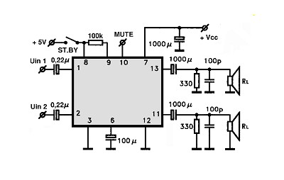
The amplifier circuit utilizing the STK4050 integrated circuit (IC) is known for its robustness and high quality. This article presents a 200-watt power amplifier circuit based on the STK4050. The circuit features an advanced auto wiring diagram with color-coded...

In this strobe light, two circuits are required: one circuit charges a capacitor to create a 320 V DC potential between the cathode and anode of the flashtube, while the other circuit generates bursts of approximately 4000 V to...
This machine utilizes the FD-CAS-923 1-stepper motor control experiment board with a 4-phase stepper motor to avoid its schematic shown in Figure 4-42a. The JK1 cop 40 core flat cable connector allows for signal arrangements compatible with EICE51 simulation...

This circuit was designed to protect a dual rail power supply from shorts across the two rails. It uses an optocoupler to monitor each supply rail, with the internal LEDs powered from ZD2 and ZD3 and the associated resistors....