
Servo Motor Controller (PIC16F84)
")
The described micro-control circuit is designed to operate a servo motor based on the input from a 3-state switch. The servo motor, which is an electromechanical device, is capable of precise angular positioning and is utilized here to achieve three distinct positions: -45 degrees, 0 degrees, and +45 degrees.
The servo motor consists of three primary connections: VCC (power supply), Ground, and a control signal wire. The control signal wire receives pulse-width modulation (PWM) signals that dictate the position of the motor. The PWM signal's pulse width is critical; it can vary between 1 millisecond (mSec) and 2 mSec. Specifically, a pulse width of 1 mSec corresponds to the -45 degrees position, 1.5 mSec corresponds to the 0 degrees position, and 2 mSec corresponds to the +45 degrees position.
The circuit's control logic is implemented using a microcontroller programmed with PICBasic. The code snippet indicates that the microcontroller is monitoring the state of the switch connected to one of its ports. The line `Symbol porta = 5` assigns the port number to a symbolic name, making it easier to reference in the code. The variable `b3 = 150` likely represents a delay or timing parameter used in conjunction with the PWM signal generation. The line `Peek porta, b0` suggests that the program is continuously reading the state of the switch connected to the specified port. The condition `If bit0 = 0` checks the state of the switch; if it is in the 'off' position, the subsequent actions (not fully shown in the provided snippet) would be executed.
In practice, the circuit would be powered by an appropriate voltage source connected to the VCC wire, while the ground wire ensures proper circuit completion. The control wire would receive PWM signals generated by the microcontroller based on the switch position, allowing for the precise control of the servo motor's angular position. This simple yet effective design is ideal for applications requiring basic angular positioning, such as robotics or automation systems.This simple micro-control circuit controls a servo motor according to a 3-state switch. A servo motor acts as an actuator in 3 position. It has 3 wires, one for VCC, one for Ground and another one for position control. The last signal is a single pulse with variable width. The pulse width can vary between 1 and 2 mSec. An 1 mSec pulse width turns the motor axis in -45 degrees position. An 1.5 mSec pulse width turns the motor axis in 0 degree position. A 2 mSec pulse width turns the motor axis in +45 degrees position. The following source code has been written in PICBasic: Symbol porta = 5 b3 = 150 start: Peek porta,b0 If bit0 = 0 Th 🔗 External reference
Related Circuits
To achieve greater sensitivity, consider using the 74AC04 or 74HC04 in place of the 74HCU04 for component U1. While the 74AC04 and 74HC04 may offer improved performance over the 74HCU04, it is important to note that the frequency response...
Sometimes, for a variety of reasons, it would be nice to vary the width of the sound stage when listening to stereo recordings. Although technically this is anything but hi-fi, it is a useful addition to PC speakers, or...
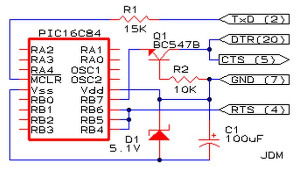
Affordable PIC Programmer. This programmer is compatible solely with the PIC16F84 microcontroller. It is reliable, as it rarely encounters errors, and functions well with nearly all computer systems, in contrast to some alternatives. The PIC programmer designed for the PIC16F84...
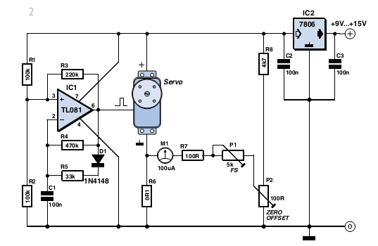
With some skill, an electronic scale can be constructed using a servo motor. Depending on the servo type, it can measure weights of up to approximately five kilograms (11 lbs) with reasonable accuracy. A detailed examination of the operating...
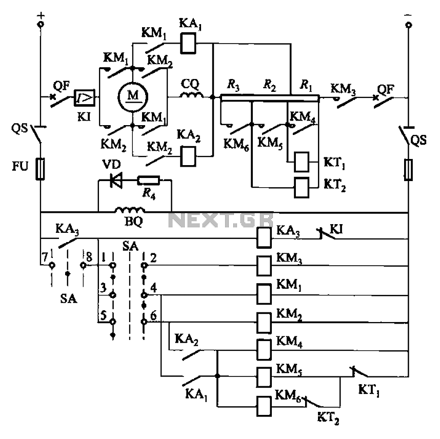
The circuit depicted in Figure 3-201 includes two starting resistors, with one controlled by a time relay. A master switch (SA) is utilized to manage the motor's reversing operation. The circuit incorporates a reverse braking mechanism, which is automatically...
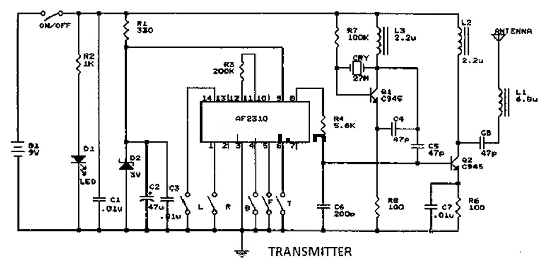
A radio control circuit designed for controlling small motors, similar to a car radio remote control toy, offers seven functions: forward, backward, left, right, left behind, right behind, and stop. The circuit requires a 27.9 megahertz frequency and a...