
Stereo Width Controllers

To implement a circuit that allows for the adjustment of the sound stage width in stereo audio systems, a simple variable resistor (potentiometer) can be utilized in conjunction with an operational amplifier (op-amp) configuration. The primary objective is to manipulate the audio signal levels of the left and right channels to create a perceived change in sound stage width.
The circuit can be designed as follows:
1. **Input Stage**: The audio input from the stereo source (e.g., PC or music center) is fed into the circuit. Each channel (left and right) should be treated separately to maintain stereo integrity.
2. **Potentiometer Configuration**: A dual-gang potentiometer is connected to each audio channel. The wiper of the potentiometer controls the level of the audio signal that is fed into the op-amps. By adjusting the potentiometer, the user can increase or decrease the gain of one channel relative to the other, effectively altering the perceived width of the sound stage.
3. **Operational Amplifiers**: Two op-amps are used, one for each channel. The op-amps are configured in a non-inverting amplifier setup. The gain of each op-amp can be set using feedback resistors, allowing for fine-tuning of the audio signal level. The output of each op-amp feeds into the respective left and right audio outputs.
4. **Output Stage**: The outputs from the op-amps are connected to the speakers. The adjusted signals will create the desired effect of widening or narrowing the sound stage based on the potentiometer settings.
5. **Power Supply**: The op-amps require a dual power supply (positive and negative) to operate effectively. A standard ±15V power supply can be utilized, ensuring that the op-amps function within their specified voltage range.
6. **Additional Features**: For enhanced functionality, a bypass switch can be integrated to allow the user to toggle between the modified sound stage effect and a direct connection to the audio source, ensuring that the original sound quality can be preserved when desired.
This circuit can be implemented on a PCB or a breadboard for prototyping, and it provides a practical solution for users who wish to customize their listening experience without compromising overall sound fidelity.Sometimes, for a variety of reasons, it would be nice to vary the width of the `sound stage` when listening to stereo recordings. Although technically this is anything but hi-fi, it is a useful addition to PC speakers, or even for the music centre in the listening room.
🔗 External reference
Related Circuits
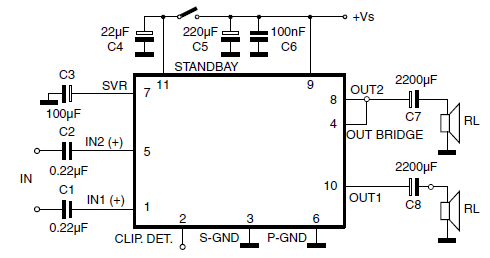
The car radio application utilizes a Class AB Audio Power Amplifier, typically featuring the TDA7360 IC. This amplifier provides 22W output in either bridge or stereo configuration and includes several beneficial features such as a minimal requirement for external...
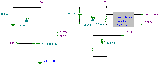
The PWM pulse width modulation controller board enables 9S12/HCS12 microcontrollers or PIC microcontrollers to output 8 channels, each capable of delivering 5 DC amps, while incorporating current sensing for the PWM waveform. This PWM driver circuit is suitable for...
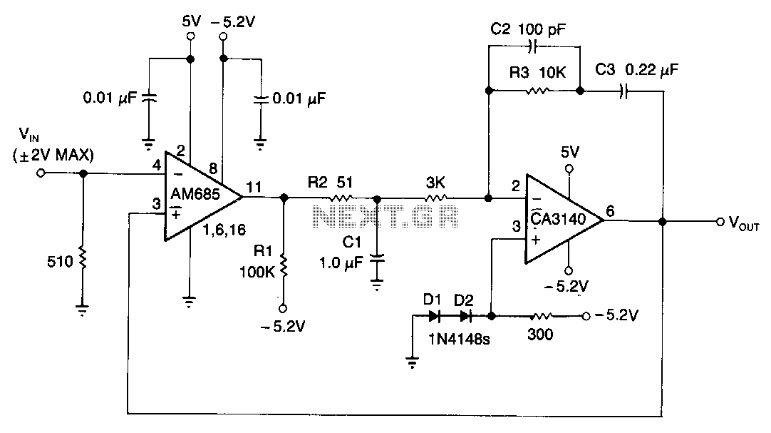
This circuit is capable of detecting positive peaks for signal frequencies exceeding 5 MHz, achieving an accuracy of ±1% for signal amplitudes ranging from 400 mV to 4 V peak-to-peak across sine, square, and triangular waveforms. The AM685 comparator...
The first half of the circuit (IC1a) features an input sensitivity of 3 mV and includes a frequency correction network consisting of capacitors C5, C3, and resistors R6 and R8. The bass signal from the phono input is amplified,...
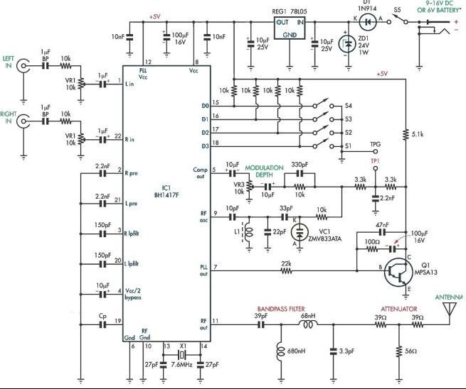
This stereo FM modulator circuit utilizes the BH1417F FM stereo transmitter IC, which includes a stereo modulator for generating stereo composite signals and an FM transmitter for broadcasting an FM signal wirelessly. The stereo modulator produces a composite signal...
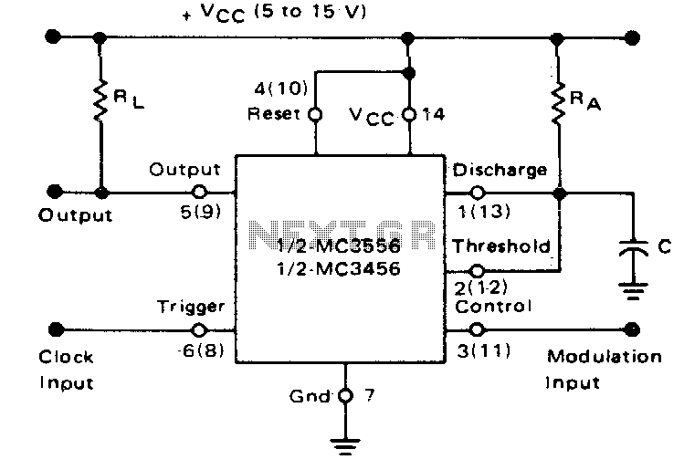
If the timer is activated by a continuous pulse train in the monostable mode, the capacitor's charge time can be adjusted by altering the control voltage at pin 3. In this way, the output pulse width can be modulated...