
servo motor pot control

A servo motor operates based on a feedback control system, which typically includes a potentiometer to monitor the angle of the motor shaft. The control signal, usually a PWM (Pulse Width Modulation) signal, determines the position of the motor. The width of the pulse corresponds to the desired angle, and the servo adjusts its position accordingly to match this input.
Servo motors are commonly used in applications requiring precise control, such as robotics, radio-controlled vehicles, and automation systems. They are available in various sizes and torque ratings, allowing for flexibility in design based on the specific requirements of the project. The typical range of motion for most standard servo motors is between 0 to 180 degrees, but there are continuous rotation servos available that can rotate indefinitely in either direction, though they do not provide positional feedback.
When integrating a servo motor into a circuit, it is essential to consider the power supply requirements, as servo motors can draw significant current during operation. Additionally, the control circuitry must be designed to handle the PWM signal accurately to ensure smooth and responsive movement. Overall, the use of a servo motor adds a high level of precision and control to various electronic projects.As part of the module one of the motors we will be using is a servo motor.A servo motor is a small motor that you can position at any angle very accurately. It contains internal circuits that will automatically maintain that particular angle. However, you cannot do full revolutions with a servo. You are restricted to.. 🔗 External reference
Related Circuits
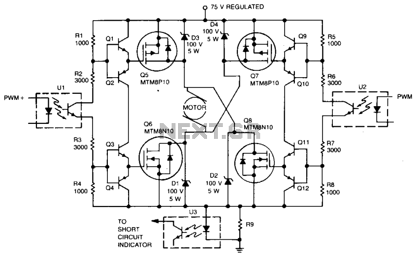
Digital integrated circuits (ICs) and opto-isolators drive this TMOS servo amplifier, resulting in fewer analog circuits and reduced drift. The fast and consistent turn-on and turn-off characteristics enable accurate analog output results directly from the digital signal without requiring...
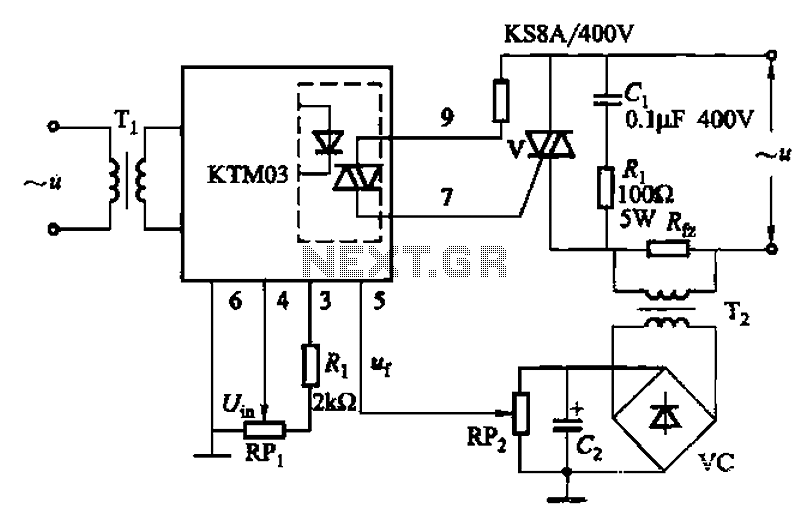
An adjustment potentiometer (RP) is utilized to set the voltage across the load resistor (Rfz) to a predetermined value. The real-time closed-loop control is achieved through the potentiometer (RPz). Open-loop control is functional as long as the feedback voltage...
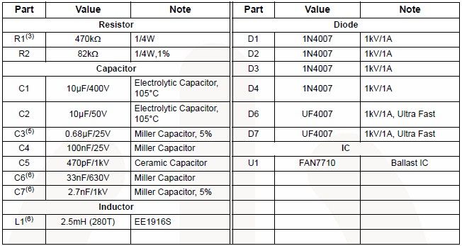
The FAN7710 Ballast Control IC for Compact Fluorescent Lamps, developed using Fairchild's unique high-voltage process and system-in-package (SiP) concept, enables the design of a simple and low-cost fluorescent lamp driver electronic project. The FAN7710 ballast control manages internal high-voltage...
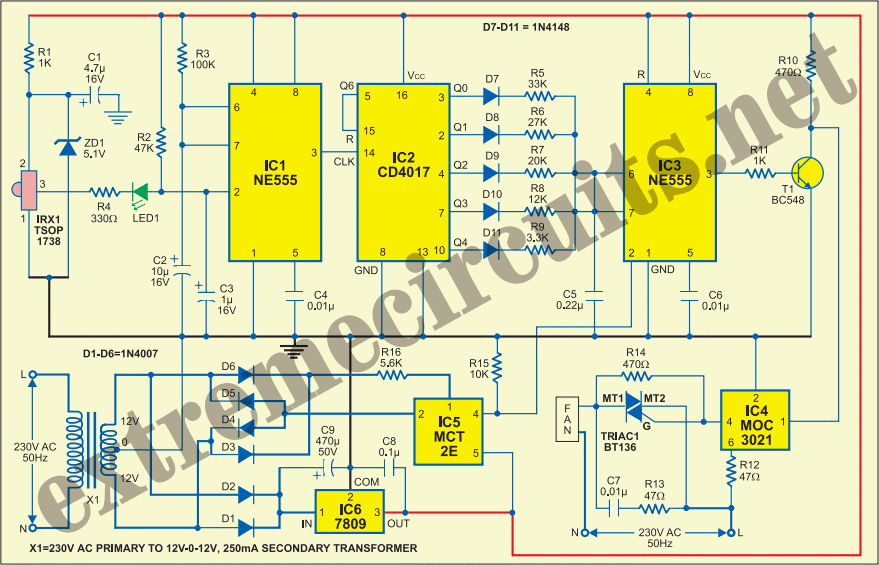
This circuit allows for the adjustment of a fan's speed from a distance, such as from a couch or bed. It utilizes an infrared receiver module TSOP1738 to capture the infrared signals sent by a remote control. The circuit...
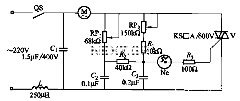
The 3P10 circuit, illustrated in the figure, utilizes a bidirectional thyristor for control. The adjustment potentiometer RPi allows for modification of the minimum motor speed, while the adjustment potentiometer RP2 enables continuous variation of the motor speed, reaching up...
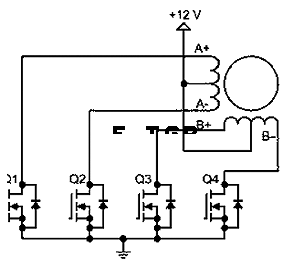
A bipolar stepper motor drive circuit is presented, utilizing eight transistors to operate two phases. This bipolar drive circuit can accommodate both four-wire and six-wire stepper motors; however, it is primarily designed for four-wire bipolar configurations, which can significantly...