
Servo Motor System Controller

The servo system controller circuit operates by generating a pulse-width modulation (PWM) signal, which is essential for controlling the position of the servo motor. The 555 timer, configured in astable mode, produces a continuous square wave output. The frequency and duty cycle of this output can be adjusted by varying the values of the resistors and capacitors connected to the timer.
To implement this circuit, the following components are typically required: a 555 timer IC, two resistors, one variable resistor (potentiometer), one capacitor, and a diode. The resistors determine the frequency of the PWM signal, while the potentiometer allows for fine-tuning of the duty cycle, thereby controlling the angle of the servo motor. The capacitor smooths the output signal, ensuring stable operation.
The output from the 555 timer is fed into the control pin of the servo motor. The servo motor interprets the width of the PWM signal to adjust its position accordingly. By changing the duty cycle, the angle of the servo can be modified, allowing for precise control in various applications, such as robotics, automation systems, and remote-controlled devices.
This circuit is advantageous due to its simplicity, low cost, and the minimal number of additional components required, making it suitable for hobbyist projects and educational purposes in understanding basic servo control mechanisms.This is a Servo System Controller circuit. This circuit is used to control a servo motor remotely. This circuit uses the 555 and requires only six extra. 🔗 External reference
Related Circuits
The figure illustrates a schematic for an oscillator amplitude-control servo system. The circuit establishes a closed-loop system that provides a fixed and adjustable peak-to-peak amplitude AC signal centered around 0 V. A 1 kHz sine wave, designated as AC_INPUT,...
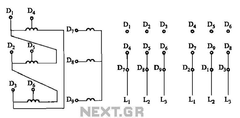
The connection of the lead wires from the stator winding of a two-speed motor to the coils is illustrated in Figure 3-109. The schematic representation of the two-speed motor's stator winding connection is critical for understanding its operational characteristics. In...
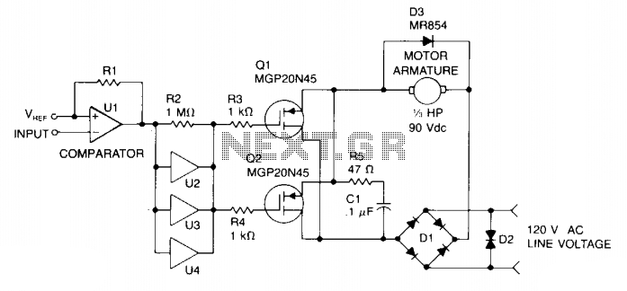
Speed control is achieved through pulse width modulation (PWM) of the gates of two MGP20N45 TMOS devices. Consequently, the motor speed is directly proportional to the pulse width of the incoming digital signal, which can be generated by a...

This simple pulse width modulation (PWM) DC motor control addresses common issues by regulating motor speed through the application of short pulses. The duration of these pulses is varied to adjust the motor speed; longer pulses result in faster...
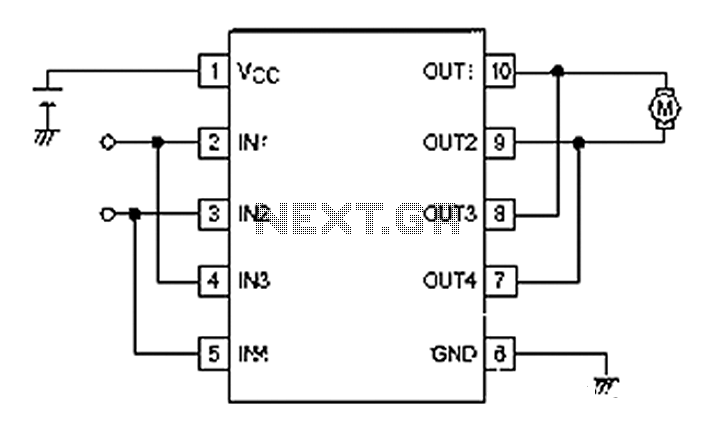
A simple motor control project for forward and backward drive can be implemented using the LB1948M motor driver IC, which features two channels for motor control. The LB1948M is an ideal choice for 12V motor drive systems and can...
Neural networks are a broad topic. This example demonstrates how to create a basic neural sensor that takes resistive readings from multiple sensors, multiplies them by a weight factor, and then sums the results. The results are compared to...