
Seven Segment LED Counter with CD4026

The circuit utilizes the 4026 integrated circuit, which is a decade counter specifically designed to drive a seven-segment display. The primary function of the 4026 is to count incoming pulses and represent the count visually on the display. The configuration of the circuit allows for simple integration with additional 4026 chips, enabling the expansion to multi-digit counting systems.
The 4026 chip operates by receiving clock pulses at its input pin, which increments the count on the display with each pulse. The output pins of the chip are connected to the segments of the seven-segment display, which light up in a specific pattern to represent the numeric value of the count. The circuit can be designed to reset the count to zero after reaching a certain number or to continue counting indefinitely, depending on the application requirements.
To expand the circuit for multi-digit counting, additional 4026 chips can be daisy-chained. The carry-out pin of the first 4026 can be connected to the clock input of the next 4026, allowing the count to propagate through multiple displays. This configuration provides a straightforward method to display larger numerical values across several digits.
Power supply considerations must be taken into account, with the 4026 typically requiring a voltage supply between 3V and 15V. Proper decoupling capacitors should be placed close to the power supply pins of the chip to ensure stable operation. Additionally, the design should include current-limiting resistors for the display segments to prevent damage from excessive current.
Overall, this circuit design offers a versatile solution for applications requiring pulse counting and visual output, with the potential for expansion to meet various counting needs.This circuit will count pulses on a seven segment display using the 4026 counter chip. It is easily expandable for multi-digit counting 🔗 External reference
Related Circuits
I needed a pulsating light for a certain signaling. Voltage was 230V. So I decided to make a simple circuit, consisted of a LED diode, two capacitors, two resistors, a diac and a diode. Activity of the circuit is...
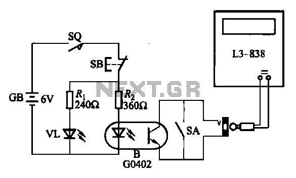
An electronic calculator features an automatic counting interface circuit, as illustrated in the accompanying figures. Figure (a) depicts a stroke switch controlled via optocoupler B. Figure (b) shows the application of a reed switch (KR) for pulse control signals....
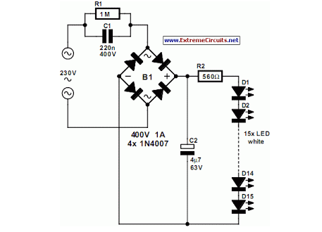
An array of white LEDs can serve as an effective small lamp for the living room. LED lamps are commercially available. LED arrays are increasingly popular for providing ambient lighting in residential spaces. The use of white LEDs in a...
This is a schematic and block diagram of a 2-MHz frequency counter. It employs an LSI counter/display driver, an LCD readout, and several logic chips for timebase and timing pulse circuitry. Transistors Q2 and Q3 form a signal input...
A keyed power input connector, series rectifier and a shunt rectifier, both 1N4007, prevent reverse voltage from being applied to the power input. A 27 volt metal oxide varistor clamps the voltage to the 78L05 that follow it, to...
The objective of this lab is to create a decimal counter that counts from 0 to 99 using the 80X51 microcontroller. A C program must be written for this purpose, which will then be compiled using the C51 compiler...