
MHz FREQUENCY COUNTER

The 2-MHz frequency counter circuit is designed to accurately measure and display frequency signals, utilizing a combination of integrated circuits and discrete components to achieve its functionality. The LSI counter/display driver is central to the operation, allowing for seamless interaction with the LCD readout. The LCD-004 display is specifically chosen for its compatibility with the ICM7224IPL, which integrates both counting and display driving capabilities, thereby minimizing the component count and simplifying the design.
The signal input amplification is critical for enhancing the weak frequency signals received. Transistors Q2 and Q3 are configured to amplify the input signal before it is processed by the counter. This amplification stage ensures that the frequency counter can accurately detect and measure lower amplitude signals, which is essential for reliable performance in various applications.
The crystal oscillator circuit, featuring U3-c and XTAL1, is responsible for generating a stable timing reference essential for frequency measurement. The oscillator operates at a fundamental frequency, which is then divided down to create additional timing references. This division is accomplished through digital logic circuits, allowing for the selection of different timing reference signals based on the application's requirements. The availability of three selectable timing references enhances the versatility of the frequency counter, making it suitable for a wider range of measurement tasks.
In summary, the design of this 2-MHz frequency counter incorporates a well-defined architecture that integrates an LSI counter/display driver, an LCD readout, and necessary logic circuitry to provide accurate frequency measurements. The use of a crystal oscillator for timing reference, along with a multi-stage signal amplification approach, underscores the careful consideration of performance and reliability in the design of this electronic measurement instrument.This is a schematic and block diagram of a 2-MHz frequency counter. It uses and LSI counter/display driver, LCD readout, and a, few logic chips for timebase and timing pulse circuitry. Q2 and Q3 form a signal (input) amplifier. The circuit contains a crystal oscillator built around U3-c and XTALl, which provides the pri-mary timing-reference signal
. That signal is then divided twice to provide two additional timing ref-erences, giving the circuitry three selectable timing references. The ICM7224IPL is an integrated circuit that consists of the counter and display driver to drive the LCD-004 display.
🔗 External reference
Related Circuits
This is a PIN diode-based RF signal attenuator circuit that operates with input frequencies ranging from 1 MHz to 500 MHz. PIN diodes are among the most commonly used components in RF applications. The RF signal attenuator circuit utilizing PIN...
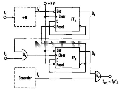
This circuit generates an output frequency that is linearly proportional to the ratio of two input frequencies. Each pulse of the bias frequency will open a switch for a period equal to half of the second input frequency, allowing...
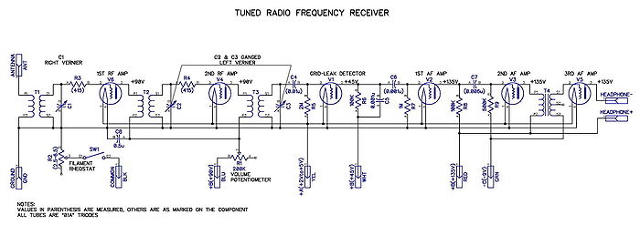
A tuned radio frequency (TRF) receiver is a radio receiver typically consisting of multiple tuned radio frequency amplifiers followed by circuits for detecting and amplifying the audio signal. A three-stage TRF receiver includes an RF stage, a detector stage,...
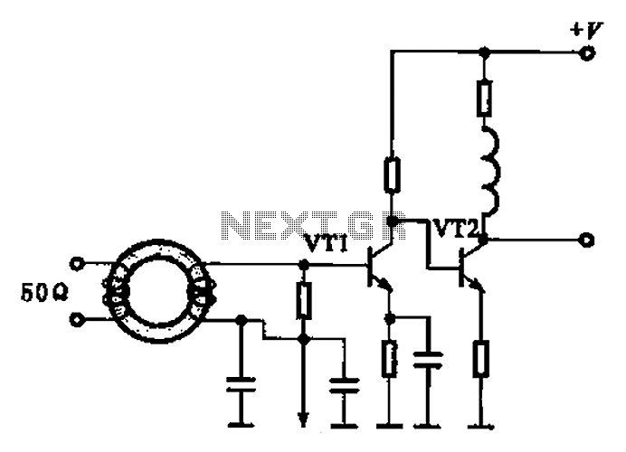
A broadband high-frequency amplifying circuit is primarily composed of a high-frequency matching transformer and an amplifying transistor. This circuit is designed to handle large high-frequency signals. The input of the amplifier circuit utilizes a matching transformer to ensure that...
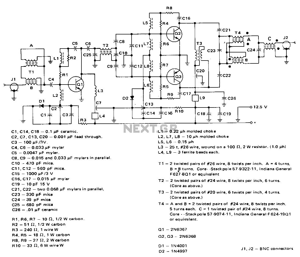
This amplifier employs a 2N6367 transistor as a driver along with a pair of 2N6368 transistors. The 2N6367 is rated for a maximum output of 9 W (PEP) and is required to deliver 5 W (PEP) at 30 MHz,...
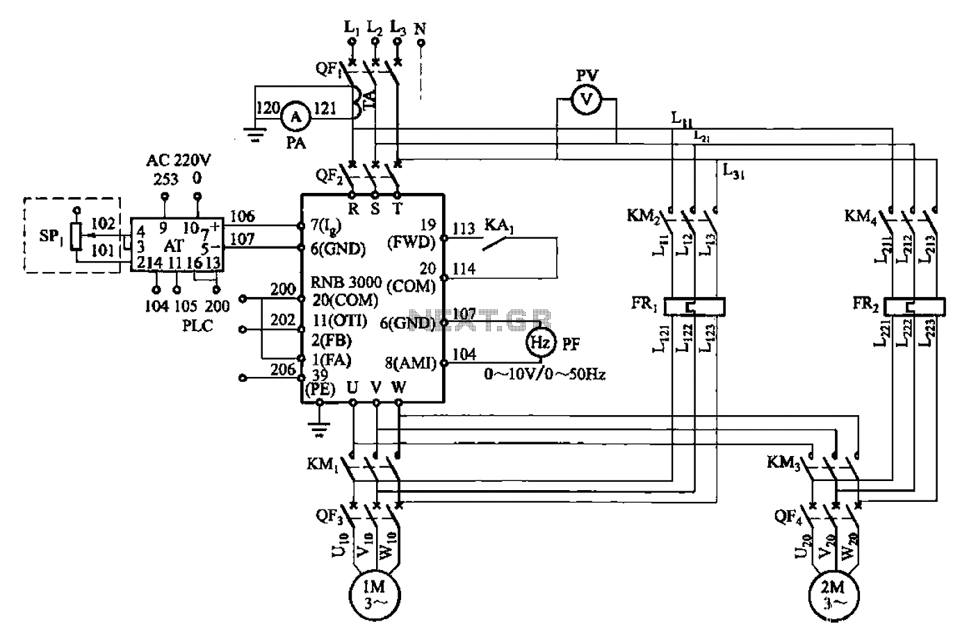
A control circuit for two motors, specifically for frequency control in a constant pressure water supply system, is illustrated in Figure 5-23. The circuit includes fault output terminals labeled 1 and 2, analog feedback current input terminals labeled 6...