
Grand Prix Starting Lights

This circuit design effectively simulates the starting light sequence used in professional racing, allowing for a visually engaging experience in model racing setups. The 555 timer serves as a reliable clock source, generating consistent pulses that drive the counting mechanism. The 4024 binary counter provides a straightforward means of counting, while the use of NAND gates ensures proper control over the counting process.
The digital-to-analog converter (DAC) implemented via the resistor ladder is a critical component, as it translates the binary count into a corresponding voltage level. This voltage is then compared against predetermined reference levels set by the voltage divider, allowing for the sequential activation of the LEDs. The choice of comparators, including the LM339 and the 741 op-amp, provides flexibility in signal processing and ensures accurate switching of the LED indicators.
The inclusion of a reset mechanism via the pushbutton switch (S1) allows for easy reinitialization of the circuit, facilitating repeated sequences without the need for manual intervention in reconfiguring the circuit. This feature enhances the usability of the circuit in various applications, including hobbyist projects and educational demonstrations in electronics. Overall, the design is efficient, straightforward, and serves as an excellent example of integrating various components to achieve a specific functional outcome in electronic circuits.This circuit reproduces the starting light sequence currently used by FISA for Formula One racing. It could be used with slot car sets (such as HO scale AFX/Life Like/Tyco sets) or radio controlled cars. IC1, a 555 timer IC, is used as a clock pulse generator. Its output is fed via NAND gates IC2a and IC2c to IC3, a 4024 binary counter. IC2b inver ts the O4 output of 4024 binary counter IC3. Initially, IC3 is reset and all its outputs are low, including O4, which causes IC2b to present a logical high to the pin 8 input of IC2c which then passes pulses from the 555 clock circuit to the clock input of the 4024. IC3 then begins counting. After the count has reached binary 1111, the next pulse sends the O4 output of IC3 high, which disables IC2c and IC3 stops counting.
The four used outputs of IC3 are connected to a resistor `ladder` which acts as a simple digital to analog convert-er (DAC). As the count increases so does the voltage produced at the top of the ladder and this is connected to the inverting inputs of four comparators inside IC4 (an LM339) and to IC5, which is a 741 op amp also connected as a comparator.
The positive inputs of the comparators are connected to the taps of a voltage divider, with the tapping voltages set using VR1, a 100kO trimpot. As IC3 counts, the rising stepped voltage from the DAC ladder switches the comparators on in sequence, starting with IC4d and working up to IC5.
As each comparator is turned on, its pair of LEDs is lit; first LEDs 1 & 2, then LEDs 3 & 4 and so on. When all five pairs of LEDs are lit, the next pulse from IC1 moves the binary count of IC3 to 10000, so the DAC voltage drops back to zero and all LEDs are extinguished.
At the same time, counting also stops, because the high on O4 causes IC2c to block further gate pulses. The circuit then remains inactive until the counter is reset by pressing pushbutton switch S1. This allows a new sequence to begin. 🔗 External reference
Related Circuits
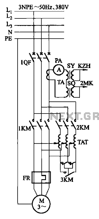
Autotransformer voltage starting, with an adjustable starting time of 30-60 seconds. It includes the SDJ electrode liquid level sensor of HJ-13 type, a pump control system box of HKD-21B type, 1MK level modules adopted by HKG-1SG type, 2MK start...
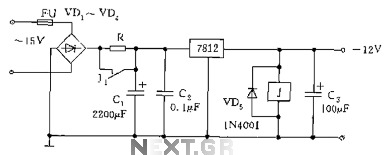
The figure below illustrates the use of a relay in the starting circuit. The power input connects through a resistor R, which serves two purposes: first, it prevents a large current from the capacitor C1 from affecting the power...
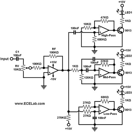
The simple circuit for converting an audio signal. The circuit basically consists of a buffer/amplifier stage and three filter circuits. The audio signal conversion circuit is designed to process audio signals efficiently while maintaining signal integrity. The circuit architecture includes...
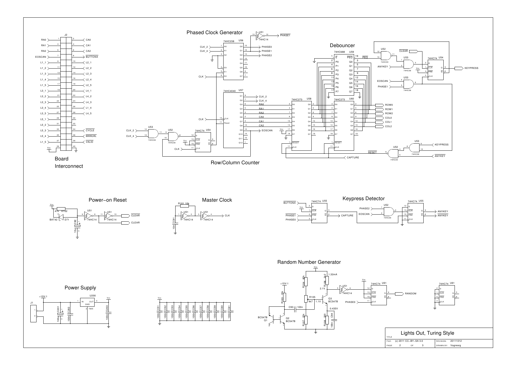
The design is based on the previous analysis of calculating the game in a circular shift register. While designing, it was realized that small extensions to the design would enable additional gameplay features, such as replay and manual input....
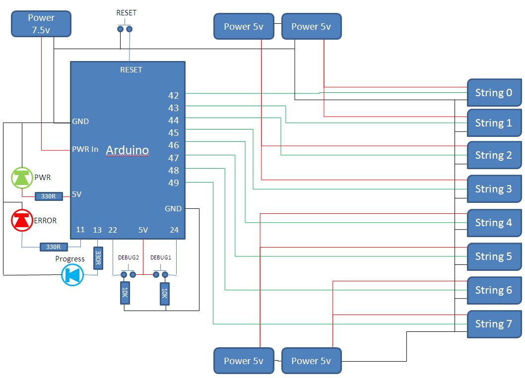
This project develops a Christmas lights controller for GE Color Effects lights, enabling programmed control of up to eight sets of lights. It includes a function-specific language for programming light patterns and an emulation environment for testing programs before...
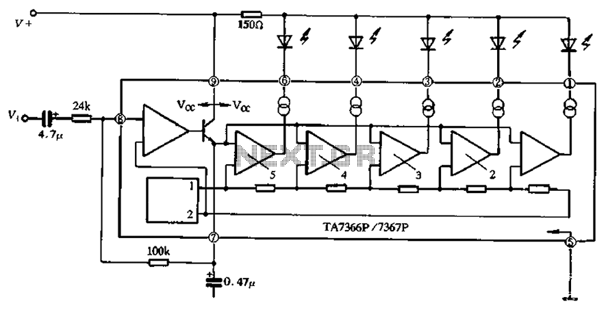
The TA 7366/7367 is a commonly used single display driver circuit manufactured by Toshiba Corporation. It features a 5 LED driver circuit and is designed in a 9-pin single in-line plastic structure. The circuit configuration includes an operational amplifier...