
SHD1006 type single positive pressure blower total pressure circuit
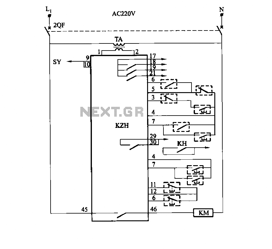
The SHD series of electronic control equipment is designed for various applications, including fan control systems. Within this series, the fan control box KZH serves a critical role, functioning as an electronic module identified as HKD 1F. This module enables precise control of fan operation, allowing for adjustments in speed and performance based on specific requirements.
The KZH fan control box incorporates several key components, including a microcontroller, power supply circuitry, and interface connections for user input and feedback. The microcontroller serves as the central processing unit, executing programmed instructions to manage the fan's operation effectively. Power supply circuitry ensures that the module receives the necessary voltage and current to function reliably.
User input can be facilitated through various interfaces, such as potentiometers for manual speed adjustments or digital interfaces for integration with automated systems. Feedback mechanisms, like temperature sensors or tachometers, may be included to provide real-time data to the microcontroller, enabling dynamic adjustments to fan speed based on environmental conditions.
The design of the KZH fan control box emphasizes efficiency, reliability, and ease of integration into existing systems. It is suitable for use in HVAC systems, industrial applications, and other environments where precise airflow control is necessary. The robust construction of the module ensures durability and longevity, making it a valuable component in electronic control systems.It uses SHD series of electronic control equipment electronic modules. Fan control box KZH as HKD 1F electronic module.
Related Circuits
Implementing peak-detector circuits is straightforward with the CA3130, as illustrated in the schematic diagram of this circuit. The figure below presents the schematic diagram. The CA3130 is a high-performance operational amplifier that is well-suited for peak detection applications due to...
This automatic NiCd charger for 9V NiCd batteries utilizes the properties of a 555 timer and is straightforward to construct. The charger is designed to automatically maintain a full charge on the battery, allowing it to remain connected for...
An FM modulator that modulates a carrier frequency with the composite signal, and an RF amplifier that provides enough power to be transmitted through an antenna. Here is the schematic diagram of the FM transmitter circuit: The core of...
A compact power amplifier that delivers high-quality sound. It incorporates a NE5534 operational amplifier, known for its excellent performance, capable of handling low loads, providing high speed, and exhibiting low distortion. Additionally, it features two V-MOSFET transistors at the...
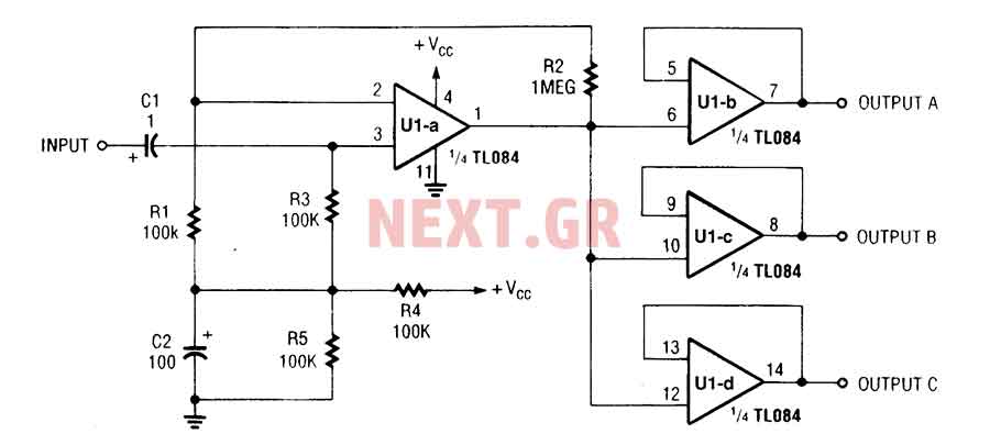
The three-channel amplifier output distribution uses a single TL084. The first step is to capacitive coupling with a 1.0 µF electrolytic capacitor. The entries are railways Vee Y2 or 4.5 V. This allows using a single 9 V power...
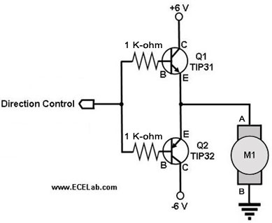
The following circuit illustrates a two-transistor DC motor driver circuit diagram. This circuit utilizes the TIP32 transistor. Features: operates in... The two-transistor DC motor driver circuit is designed to control the operation of a DC motor using two NPN transistors,...
Warning: include(partials/cookie-banner.php): Failed to open stream: Permission denied in /var/www/html/nextgr/view-circuit.php on line 713
Warning: include(): Failed opening 'partials/cookie-banner.php' for inclusion (include_path='.:/usr/share/php') in /var/www/html/nextgr/view-circuit.php on line 713