
PC Watcher | Turn On and youll hear the Alarm

The PC Watcher circuit operates by monitoring the status of the computer and detecting any unauthorized attempts to access it. The circuit typically includes a microcontroller, which serves as the central processing unit, and various sensors or inputs that can detect physical access or intrusion attempts.
The components may include a motion sensor, a door contact switch, or a keypad that requires a code for access. When unauthorized access is detected, the microcontroller can trigger an alarm or send a notification, providing an immediate response to potential security breaches.
Power supply requirements for the circuit are usually modest, allowing it to be powered through the computer's USB port or a dedicated power adapter. The circuit can be compactly designed to fit within the confines of a small enclosure, making it suitable for integration into existing computer setups without occupying much space.
For installation, the circuit can be connected to the computer's case or positioned near entry points to the workspace. The veroboard layout should be organized to minimize interference and ensure reliable connections between components. Proper soldering and secure mounting of components on the veroboard are crucial to maintain the integrity and functionality of the circuit.
Overall, the PC Watcher circuit is an effective solution for individuals seeking to enhance their computer security by providing a simple yet effective means of monitoring unauthorized access attempts.This little PC Watcher circuit will help you to prevent unauthorised access to your personal computer. After construction on a small piece of veroborad, en.. 🔗 External reference
Related Circuits
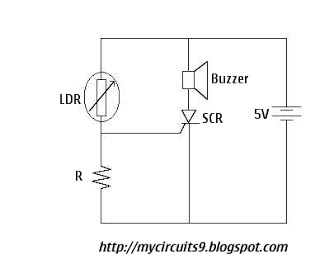
The Light Dependent Resistor (LDR) is a variable resistor whose resistance decreases as light intensity increases. Under normal light conditions, the resistance of the LDR is sufficiently high, resulting in an inadequate voltage across resistor R to activate the...
This circuit detects when a tube is empty and pulses a piezo buzzer at 5-second intervals. It is currently operational with a 5V supply on a breadboard but needs to be adapted for a 12V supply from a wall...

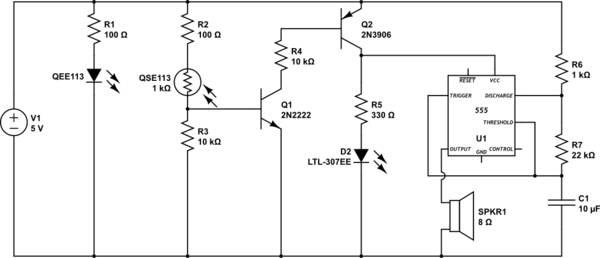
The simple circuit generates an audible alarm notification, functioning as a burglar alarm utilizing five transistors. This circuit operates as a basic burglar alarm system designed to emit an audible sound when triggered. The core component of the circuit is...

This light alarm schematic circuit is designed using common electronic components, as illustrated in the circuit diagram below. The light alarm circuit will activate an alarm as soon as the drawer is opened and light falls on the Darlington...
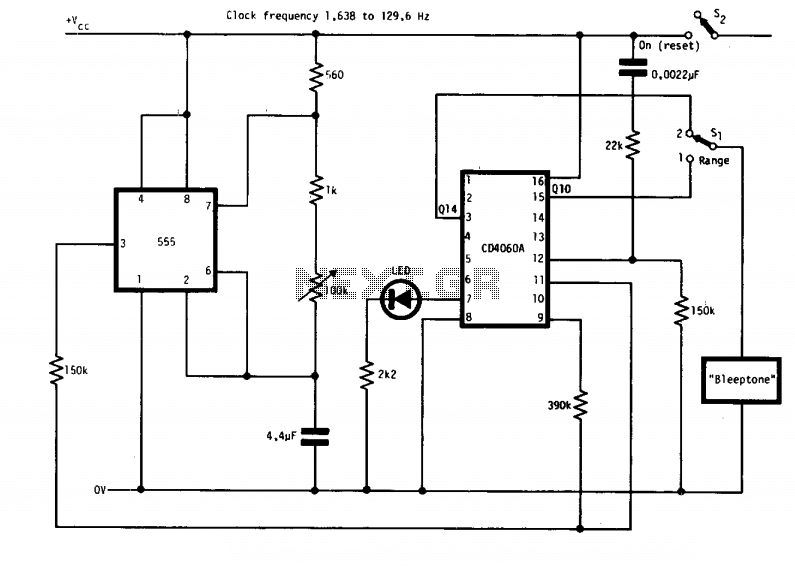
The circuit features two timing ranges: from 10 seconds to 5 minutes and from 1 minute to 80 minutes. It is powered by a 9-V battery. An LED is connected in a manner that allows for a consistent flashing...

This car headlight alarm circuit can be configured for one or two functions: First, it indicates that the headlights (or the side lights) should be turned off after the ignition is switched off. With this circuit, there should be...