
water level alarm circuit

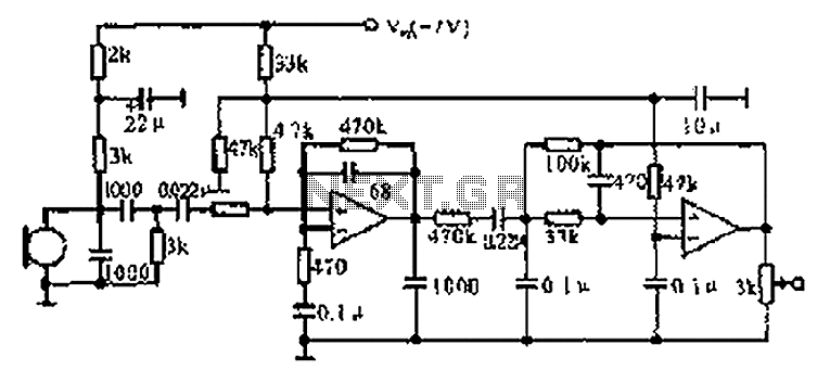
The water level alarm circuit typically consists of a few key components: two conductive probes, a comparator or operational amplifier, a resistor, a piezo buzzer, and a power supply. The probes are positioned at specific heights to detect the water level. When water bridges the gap between the probes, it completes the circuit, allowing current to flow.
The operational amplifier is configured as a comparator. It compares the voltage across the probes with a reference voltage set by a resistor divider network. If the voltage from the probes exceeds the reference voltage, the output of the comparator switches state, activating the piezo buzzer. This buzzer generates an audible alarm, alerting users to the water level condition.
The circuit is powered by a suitable DC power supply, which can range from 5V to 12V, depending on the components used. Proper placement of the probes is crucial; they should not be too close to prevent false triggering due to minor fluctuations in water levels. Additionally, the probes must be made of a corrosion-resistant material to ensure longevity, especially in environments with varying water quality.
This water level alarm circuit can be effectively used in various applications, including monitoring water levels in tanks, aquariums, and swimming pools, providing a practical solution for water level management.Here is the schematic of a water level alarm circuit. The circuit will work as a water level sensor and will give a melodious alarm sound when the two probes in the circuit will detect water. You can use this water level indicator circuit to detect the level of water in any place for example in swimming pool, For using the circuit simply attach th
e two probes on the desired level of water on which you want the indication and make two to three inches gap between the two probes. 🔗 External reference
Related Circuits
The CX9800 models of mobile phones and desktop PCs feature a high-performance voice processing circuit that compresses the amplitude and bandwidth of the microphone signal. This design enhances the sensitivity of the microphone and its adaptability to varying distances....
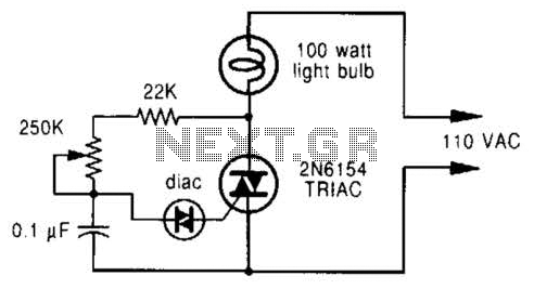
A phase-controlled dimmer delays the triac turn-on to a selected point in each successive AC half cycle. This circuit is suitable only for incandescent lamps, heaters, soldering irons, or universal motors that have brushes. A phase-controlled dimmer is an electronic...
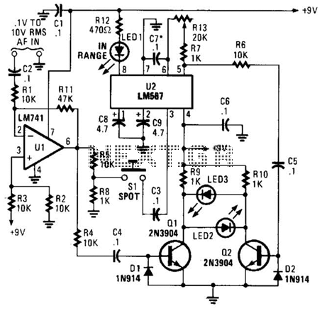
This meter is unique as it does not utilize a D'Arsonval movement or digital display for frequency readings. Instead, the measured frequency is indicated on a hand-calibrated dial. Any audio signal applied to the circuit is amplified by U1,...
This characterization circuit, along with a PC and specific software, accurately measures the complete discharge cycle of a rechargeable AA cell. The capacity and output resistance of the cell can be easily determined from the resulting curve of these...
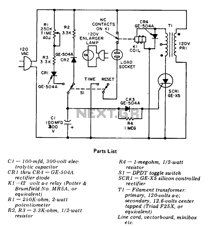
This precision solid-state time delay circuit features both delayed off and delayed on switch functions, which can be interchanged by simply swapping the relay contacts. The described time delay circuit is designed to provide precise control over the timing of...
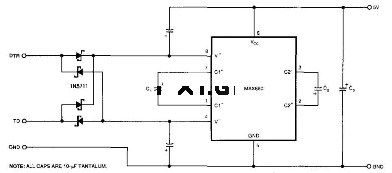
The circuit demonstrates a method for powering CMOS integrated circuits (ICs) using RS-232C lines. The MAX680 is typically employed to generate a voltage equal to ±2 Vcc. This circuit operates in the opposite manner, accepting ±10.5 to ±12V from...