
Shield drive by the PGA204 / 205 configuration circuit

The described circuit serves as a shield drive mechanism, employing the OPA177 operational amplifier to enhance signal integrity in environments susceptible to electrical interference. The PGA204 and PGA205 serve as programmable gain amplifiers, providing the necessary amplification to weak input signals. The operational amplifier OPA177 is configured as a voltage follower, ensuring that the output voltage closely follows the input voltage, which maintains the potential of the shield.
This arrangement is critical in applications where cable shielding is necessary to mitigate noise and interference, particularly in sensitive measurement systems. By elevating the shield to the same potential as the output of the instrumentation amplifier, the circuit minimizes the potential difference that could lead to unwanted coupling and interference. The design effectively leverages the principles of interference theory and distributed capacitance to improve the performance and reliability of signal transmission in challenging environments.
The implementation of this circuit can be found in various applications, including audio processing, data acquisition systems, and instrumentation where maintaining signal integrity is paramount. Careful attention to the layout and grounding of the circuit is essential to maximize the benefits of the shield drive configuration, ensuring optimal performance in reducing noise and interference.As shown by PGA204 / 205 to the shield drive circuit of FIG. As evidenced by the interference theory and practice, the cable shield weak signal transmission with a certain potential, it will greatly reduce interference between the shield and the core introduced by the distributed capacitance coupling. The circuit in Figure is based on this consideration, constitute an op amp OPA177 shield drive, the input signal from the PGA204 / 205, after OPA177 by the voltage follower output to the shield that the shield is raised to the potential of the internal instrumentation amplifier potential of the output of the op amp, so the cable line interference is greatly reduced.
Related Circuits
A problem has been encountered in a Phase-Locked Loop (PLL). A loop filter has been utilized, but the output spectrum does not meet expectations. In a Phase-Locked Loop (PLL) system, the loop filter plays a crucial role in determining the...
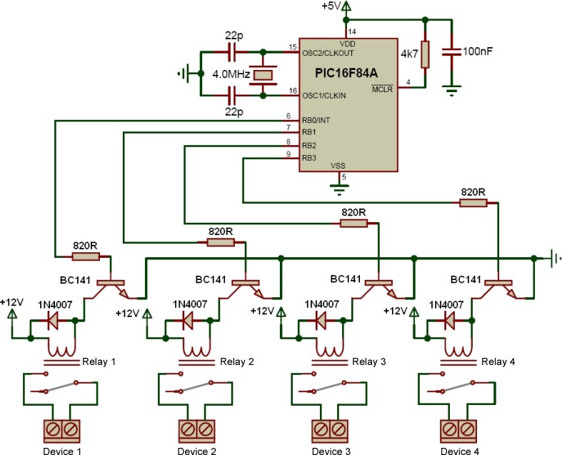
The transformer is a 220V to 12V, 50Hz, and 3.6VA PCB type transformer. The model depicted is HRDiemen E3814056. Being encapsulated, it is isolated from external influences. A 250V 400mA glass fuse protects the circuit from damage caused by...
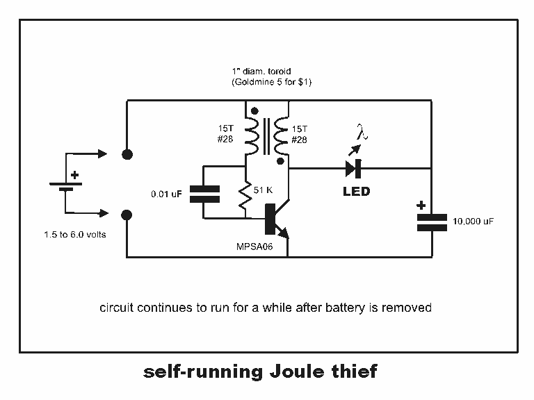
Professor Steven E. Jones' circuit demonstrates an 8x overunity. The concept of overunity refers to a system that produces more energy than is consumed, effectively achieving a coefficient of performance greater than one. In the context of Professor Steven E....
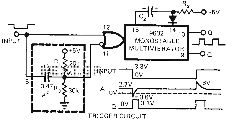
The 9602 multivibrator circuit can trigger either the rising edge or the falling edge of a square wave, but not both simultaneously. To enable double-edge triggering, two additional resistors and a capacitor can be employed. When the input signal...
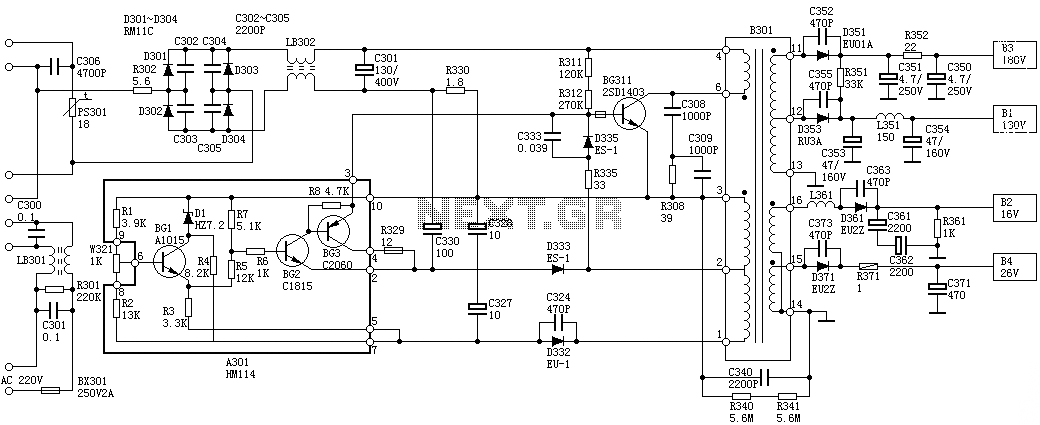
Oscillation: The positive terminal voltage of C310 is approximately 300V. The resistors R311 and R312 are connected to the switch BG311 at the B pole, while the B301 winding via the switching transformer (4) and (6) is connected to...
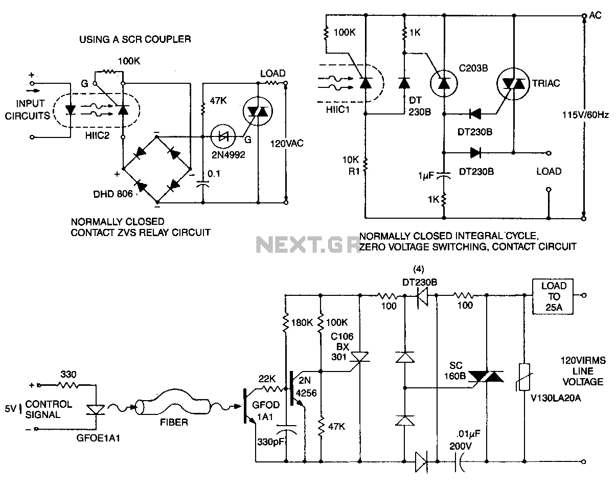
This circuit is effective for lamp and heater loads. Some circuits driving reactive loads require integral cycling and zero-voltage switching when an identical number of positive and negative half-cycles of voltage are applied to the load during a power...