
Bedside Lamp TimerCircuit Based On The CD4060 IC

The Bedside Lamp Timer Circuit utilizes the CD4060 IC, which is a versatile component capable of generating a range of timing intervals. The circuit is designed to control the illumination of an LED, which serves as an indicator or as part of a bedside lamp setup. When activated, the circuit allows the LED to remain lit for about 25 seconds before automatically turning off, providing a convenient way to light a room without the need for manual operation.
The CD4060 is a 14-pin IC that includes an oscillator and a binary counter. In this application, the oscillator generates a clock signal, which is fed into the binary counter. The counter is configured to count a specific number of cycles before triggering the output to turn off the LED. External components such as resistors and capacitors are connected to the CD4060 to set the timing interval. The values of these components can be adjusted to modify the duration for which the LED remains illuminated.
For practical implementation, the circuit may include a switch to activate the timer and a power source, typically a low-voltage DC supply. The LED is connected to the output pin of the CD4060, ensuring that it receives the necessary current to illuminate. The circuit can be housed in a suitable enclosure, making it a practical addition to bedside lighting solutions.
This timer circuit not only enhances convenience but also contributes to energy savings by ensuring that the lamp is not left on indefinitely. Overall, the Bedside Lamp Timer Circuit based on the CD4060 IC is a practical and efficient solution for automated lighting control.The following circuit shows about Bedside Lamp Timer Circuit Diagram. This circuit based on the CD4060 IC. Features: LED illuminates for around 25 .. 🔗 External reference
Related Circuits

Utilizing the ATmega 2560, which serves as the core of the Arduino platform, a universal remote control with GSM capabilities has been developed. This device allows for the control of 2 inputs and 2 outputs, DTMF key functionality, gate...

The circuit is economical in components and can operate with virtually any transistors, ensuring reliable self-starting functionality. The voltage Vb can be derived from a voltage divider, as illustrated. However, if Vb is sourced from a fixed voltage, the...
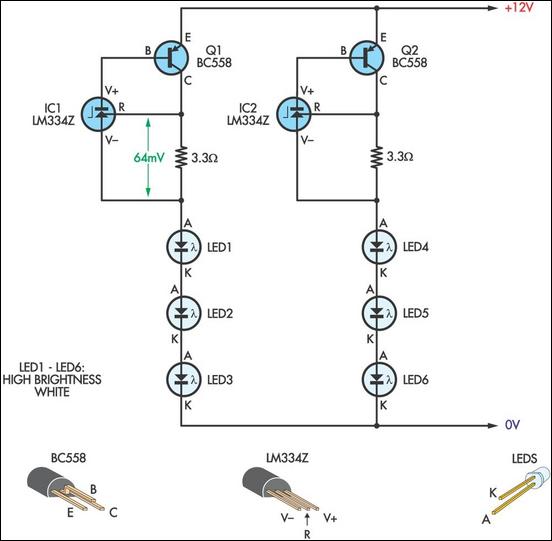
This LED lamp was originally designed for use on a budget solar-charged 12V electrical system. It is bright enough for comfortable reading at night and features constant LED brightness with diminishing battery voltage. The circuit uses six high-brightness white...
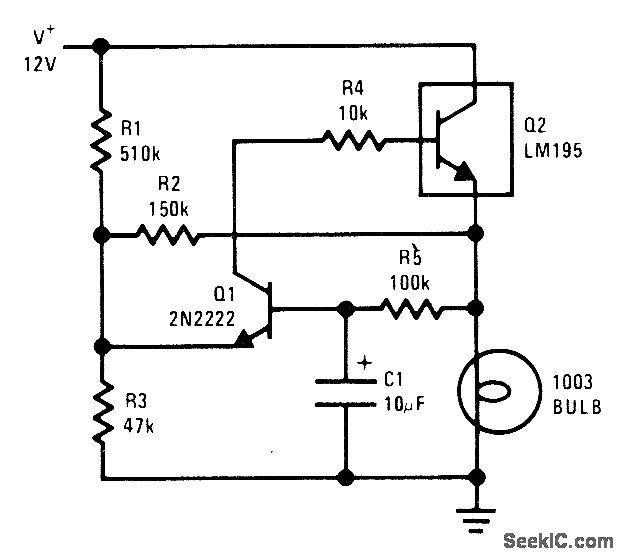
The National LM195 power transistor is activated and deactivated once per second to flash a 12-V lamp. The current limiting feature of the LM195 prevents high peak currents during turn-on, even when a cold lamp can draw up to...

A technique for measuring frequencies across a wide range with acceptable accuracy using a PC is described. This method involves measuring the period of a complete wave at low frequencies to calculate frequency from the measured time period. Cascaded...
Flashing frequency can be varied by changing R1 value in the 1M - 4M7 range. This circuit is very efficient when driving a small 3.2V incandescent lamp. In this case omit the LED and R3, connecting the bulb across...