
Shortcircuit protected voltage regulator

The described voltage regulator circuit utilizes a combination of a voltage regulator IC, such as those from the LM7805 or LM7812 series, along with additional components to enhance its functionality and provide short-circuit protection. In this configuration, T1 serves as a current limiting transistor, which is crucial for preventing excessive current flow during fault conditions. The operation of T1 is governed by the voltage across resistors R2 and R3; when this voltage exceeds approximately 0.6 to 0.7 volts, T1 activates, cutting off the base current to T2, thereby disabling it and preventing further current flow.
The resistors R3 and R4 are configured as a voltage divider that sets the base voltage for T2, which is essential for regulating the output voltage. If the output experiences a short circuit, the current through R2 and R3 will increase, triggering T1 and protecting the circuit from damage due to overheating. The design effectively manages power dissipation, which is a critical consideration in voltage regulator applications, especially when high currents are involved.
For applications requiring higher output currents, the addition of a complementary transistor, T2, is necessary. This transistor can handle increased load demands, allowing the circuit to provide up to 3 A of output current. The design ensures that even under fault conditions, the circuit remains stable and safe, making it suitable for a variety of applications where reliable voltage regulation is required.At this voltage regulator prototype the maximum current, with output shortcircuited it was only 0,5 A, so no overheating occured. In this dc voltage regulator circuit, T1 is for current limitation. As soon as the voltage on the R2+R3 becomes higher than 0,6-0,7 V, T1 opens, which leads to a reduction to zero of the T2 base current.
The voltage at which the shortcircuit protection starts to act, is given by voltage sum on R2 and R3. R3 and R4 resistances form a T2 voltage divider. Voltage regulator IC’s, with 3 pins, from LM7805 and LM7812 series are excellent for usage in voltage regulator circuits. If you need higher currents, up to 3 A, you must add a complementary transistor, T2 in this schematic.
In a normal design, in case of a shortcircuit, the power dissipation can be very high. This problem can be solved using the voltage regulator design presented bellow. 🔗 External reference
Related Circuits
An integrated voltage regulator connected in reverse to a mini drill allows for speed adjustment within specific limits, maintaining a constant speed regardless of load. The electronic speed control is achieved through a voltage regulator, which can power motors...
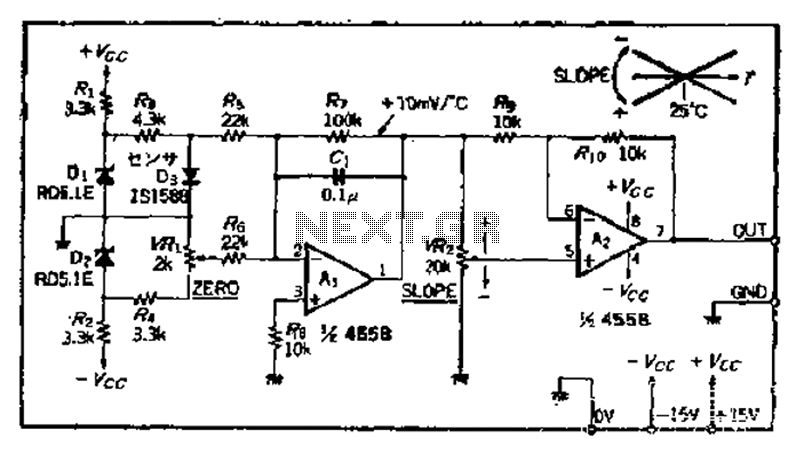
A temperature sensor can be created using a standard silicon diode, which produces approximately 2.2 mV per degree Celsius variation. An operational amplifier (OP amplifier) is utilized with a positive reference temperature (room temperature). The output signal is amplified...
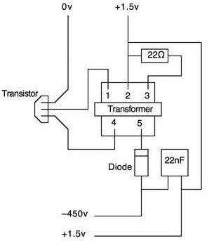
This article outlines a straightforward and effective method for deterring intruders. While alternative methods exist, this approach is suitable for office pranks and general amusement. The project necessitates a basic understanding of electronics and circuitry, including the ability to...
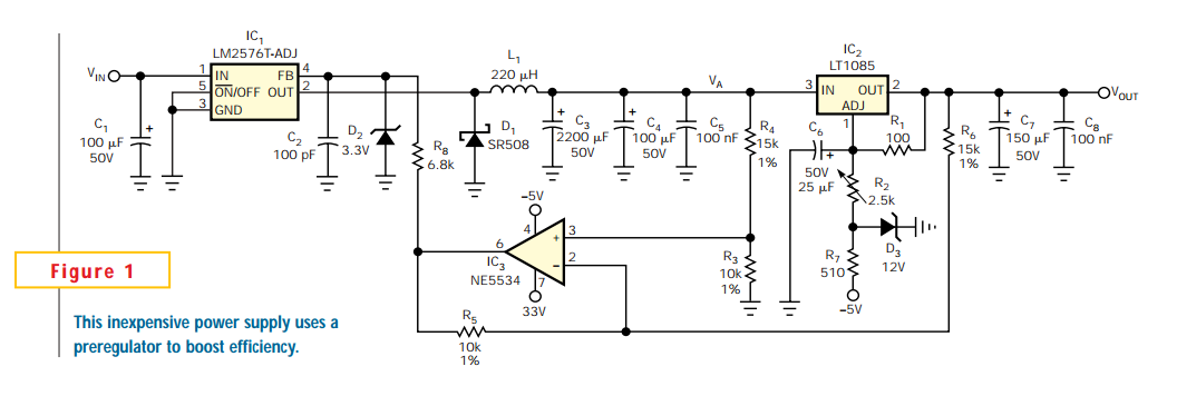
Linear regulators are easy to implement and have better noise and drift characteristics than switching approaches. Their largest disadvantage is inefficiency: excess energy dissipated as heat. Several well-known techniques are available to minimize the input-to-output voltage across a linear...
Automatic AC voltage regulator circuit TXD1742 with continuous adjustment. The TXD1742 is an automatic AC voltage regulator circuit designed to provide continuous voltage adjustment, ensuring stable output voltage in varying load conditions. This circuit is particularly useful in applications where...
Project Manager Jim Heck, G3WGM, has provided an exclusive audio interview to Bob McCreadie, G0FGX, from TX Factor, detailing the tests and potential issues involved. Membership in AMSAT-UK is available to anyone interested in amateur radio satellites or space...