
Shortwave Monitor

This receiver circuit is structured around two primary amplification stages: a radio frequency (RF) amplifier and an audio frequency (AF) amplifier. The RF amplification is handled by the CA3089 integrated circuit, which is optimized for FM applications, but in this case, the FM functionality is not implemented. Instead, the circuit leverages the internal level detector of the CA3089 to produce a robust output signal suitable for driving an audio amplifier without requiring intermediate stages.
The audio amplification is managed by the LM386, a low-voltage audio power amplifier that is well-suited for battery-operated devices. The LM386 can efficiently drive an 8-ohm load, such as a loudspeaker or headphones, ensuring that the audio output is clear and sufficiently loud for monitoring purposes. The choice of a 9 V power supply aligns with the circuit's design, allowing for optimal performance while maintaining low power consumption, which is advantageous for prolonged usage with battery power. The circuit's ability to operate down to 5.5 V provides flexibility in terms of power supply options, enhancing the longevity of the battery life.
A crucial component of the receiver's performance is the antenna, which is pivotal for capturing the short-wave signals. The recommended experimentation with wire lengths suggests that while a 50 cm wire can provide acceptable results, extending the antenna to a range of 5 to 15 meters is likely to yield improved reception quality. This adaptability in antenna design allows users to optimize their setup based on specific environmental conditions and reception requirements.
Overall, this receiver circuit is an effective tool for short-wave listening and ionosphere monitoring, combining simplicity in design with practical functionality. It serves as an excellent project for electronics enthusiasts interested in exploring radio frequency applications and audio amplification techniques.This receiver not only gives a good indication of the myriad of stations on offer in the short-wave band but is also an excellent tool for monitoring the state of the ionosphere. The circuit actually consists of no more than an RF and an AF amplifier. The high-frequency amplification is carried out by the IF stage of a CA3089. This IC is actually intended for FM receivers, but the FM section is not used here. The internal level detector provides a signal of sufficient strength to drive an audio amplifier directly. An LM386 was selected for this task. This IC can directly drive an 8- loudspeaker or headphones without any difficulty. The power supply voltage is 9 V. Because of the modest power consumption a 9-V battery is very suitable. In addition, the circuit will work down to a voltage of about 5. 5 V, so that the battery life will be extra long. The antenna will require a little experimentation. We obtained reasonable results with a piece of wire 50 cm long. A length of wire in the range of 5 to 15 meters should provide even better results at these frequencies.
Be the first of your friends to get free diy electronics projects, circuits diagrams, hacks, mods, gadgets & gizmo automatically each time we publish. Your email address & privacy are safe with us ! 🔗 External reference
Related Circuits
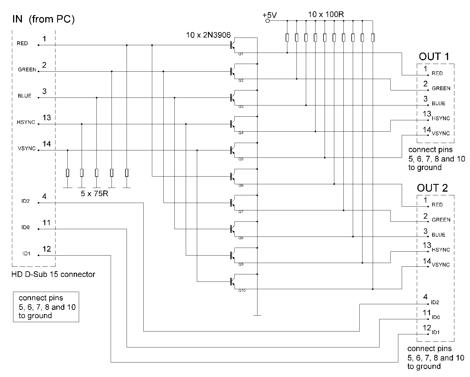
The signal sources in the analog output stage of the PC SVGA card are designed to present the correct impedance of 75 ohms on each line, utilizing five resistors. The input impedances of the transistors are sufficiently high to...

Getting microprocessor designs to function correctly is often challenging, particularly when both the software and hardware are unfamiliar. The typical method involves executing test routines that target memory and I/O without relying on their proper operation. However, any miswiring...

This is an experimental work to monitor a spectrum pattern of radio band, and is a continuous project from Audio Spectrum Monitor. To analyze the spectrum of an input signal, I chose an Atmel's AVR microcontroller used in Audio...
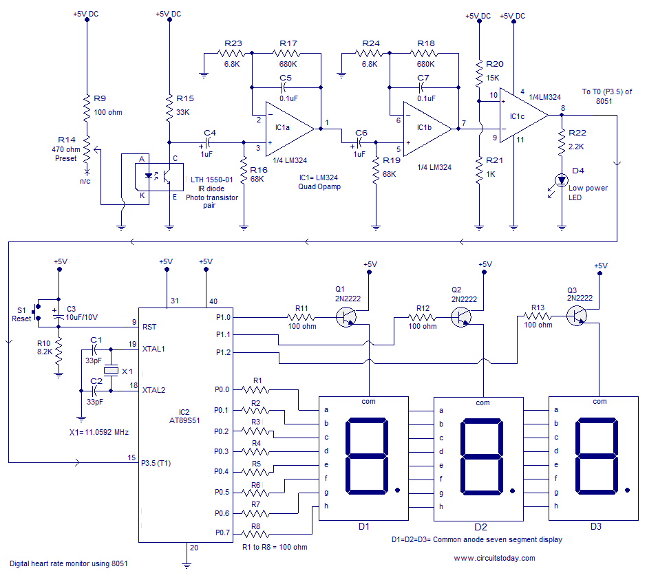
Heart rate monitor using an 8051 microcontroller. It measures the heart rate from the fingertip using an IR diode and phototransistor pair (Photoplethysmography). The AT89S51 microcontroller is utilized in this application. The heart rate monitor circuit operates based on the...
Video signals can be challenging to display on an oscilloscope. Standard trigger circuits in most oscilloscopes often struggle to achieve a stable trigger from the combined vertical and horizontal sync signals, color burst, and picture signal found in a...

This circuit is designed for monitoring automotive lighting. Two specialized integrated circuits (ICs) from Telefunken are used to measure the current through a light bulb. Detecting whether current flows through a bulb is an effective method to determine its...