
Signal Conditioners Information

Signal conditioning is a critical aspect of interfacing sensors with digital systems, ensuring that raw data is transformed into a format that can be effectively processed and utilized. The integration of signal conditioners in a circuit plays a pivotal role in enhancing the accuracy and reliability of measurements obtained from various sensors.
The choice of filtering method is essential for optimizing the performance of the signal conditioning circuit. For instance, low-pass filters are particularly effective in applications where high-frequency noise may interfere with the desired signal, such as in temperature sensing or pressure measurements. Conversely, band-pass filters are useful in applications like audio processing, where signals of specific frequency ranges are of interest, allowing for selective amplification and processing of those frequencies while attenuating others.
Amplification stages within the signal conditioning circuit also require careful consideration. The selection of the appropriate type of amplifier depends on the specific requirements of the application. For example, instrumentation amplifiers are ideal for applications requiring high input impedance and low output noise, making them suitable for interfacing with high-impedance sensors. Isolation amplifiers, on the other hand, are critical in applications where electrical isolation is necessary to prevent ground loops and protect sensitive components.
In summary, the design and implementation of signal conditioning circuits involve a comprehensive understanding of filtering, amplification, and conversion processes. These elements work together to ensure that sensor outputs are accurately transformed into usable signals for further analysis and interpretation, thereby enhancing the overall functionality of electronic systems.Signal conditioning is a set of operations performed on a signal that makes it suitable for interfacing with other devices or systems. Signal conditioners are the actual devices that perform this operation. These devices have an input and an output. Normally the input is a sensor that measures a variable, not necessarily and electrical signal. The signal conditioning process is also knownas atransfer function because the final effect is to convert an input signal (or measurement) into a suitable output signal. For instance, when a temperature sensor measures the temperature of a system or environment, the output of the sensor (temperature) is not suitable to be an input signal to an electrical system.
Therefore, the temperature measurement must be converted into an electrical signal. Signal conditionersprovide filtering, amplification, converting, and / orother processes required to make sensor outputs suitable for reading by computer boards. They areused primarily for data acquisition, in which sensor signals must be normalized and filtered to levels suitable for analog-to-digital conversion.
The digital signal is then available tobe analyzed or interpreted by a computerized device. Filters can be constructed from either active or passive components. A passive filter uses only resistors, capacitors, and inductors with a maximum gain of one. An active filter uses passive components and active components like operational amplifiers and transistors. They have a higher gain with sharper frequency response curves. Analog (RC) - Analog filters are designed with resistors and capacitors. They are used for analog signals only, and are often used in low-noise requirement applications. Digital (FIR, IIR) -Digital filters are designed with solid-state components and used for digital signals and quantized signals from a sample-and-hold amplifier.
This category includes finite impulse response (FIR) and infinite impulse response (IIR) filters. Digital filtering can approach ideal bandpass characteristics. The function of the filter is to separate the signal`s frequency spectrum into valid datawhile blockingnoise. The standard types of filter responses are low-pass, high-pass, band-pass, and band-reject (or notch filter).
Filters are selected based on the frequency of the signal to be analyzed. Low-pass filters block high frequency components; or allow the passage of low frequency signals. A simple passive low-pass filter can be constructed with only a resistor and a capacitor. Band-pass filters allow the passage of signals within a range of frequencies and blocks signals with frequencies below the smallest frequency in the range and above the highest frequency in the range. If the range (band) of frequencies is between f1 and f2 then the filter allows the passage of signals with frequencies between f1 and f2 only.
Band-notch filters, alsoknown as a band-reject filters, allow the passage of all frequencies with the exception of signals within a range of frequencies. Amplification is a process which increases (amplifies) the signal for possessing or digitization. Signal amplifiers often include electronic components that amplify signals without producing significant amounts of thermal noise.
In some applications a signal must be amplified or attenuated in order to drive a circuit or a system. There are many types of amplifiers used in signal conditioning including the following: Voltage followers have a unity gain, so the output signal is a reproduction of the input signal.
This type of amplifier is mainly used as an impedance matching device. Isolation amplifiers are designed specifically to isolate high DC levels from the data acquisition device while passing the relatively small AC or differential signal. The inputs and outputs are electrically isolated. Instrumentation amplifiers are differential amplifiers that have been optimized for use with DC signals.
They are characte 🔗 External reference
Related Circuits
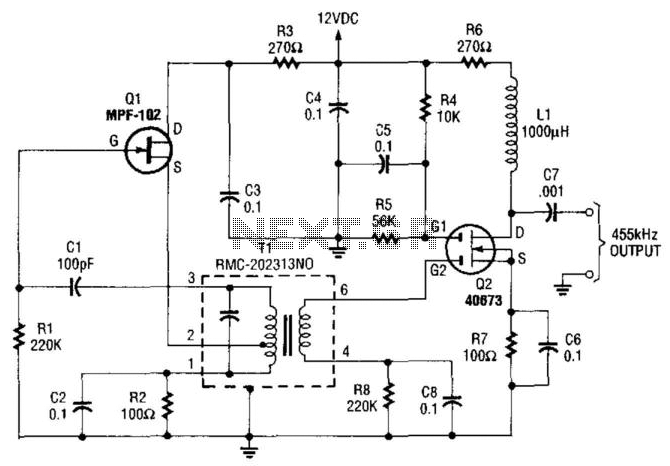
An MPF102 FET oscillator drives a dual-gate MOSFET buffer. The MPF102 is configured as a Hartley oscillator. If desired, an audio voltage can be coupled to the junction of R4, R5, and C5 with an extra coupling capacitor (~1...
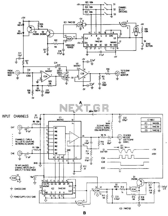
In the video system illustrated in Figures A and R, a single coaxial cable transmits power to a remote location, selects one of eight video channels, and returns the selected signal. This system can choose from several remote surveillance...
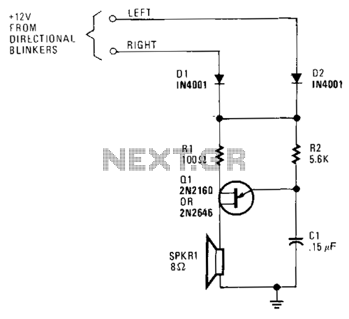
A unijunction transistor audio oscillator drives a small speaker. The oscillator's frequency is determined by resistor R2 and capacitor C2. The operating voltage is supplied from the car's turn-signal circuit(s) through D1 and D2. The diodes conduct current from...
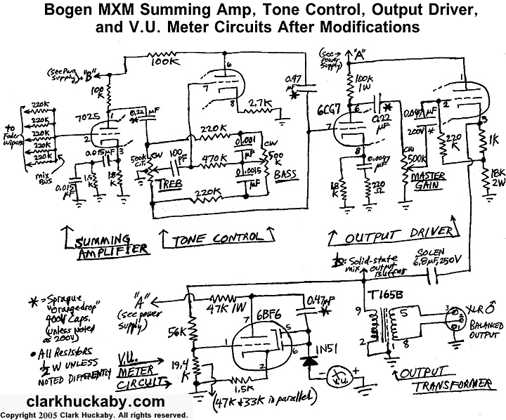
The block diagrams presented in Figure 1 indicate that the overall signal flow in this five-input mixer underwent minimal changes following modifications. Solid-state buffers were added to provide independent direct outputs for the five preamp channels. The audio signal...
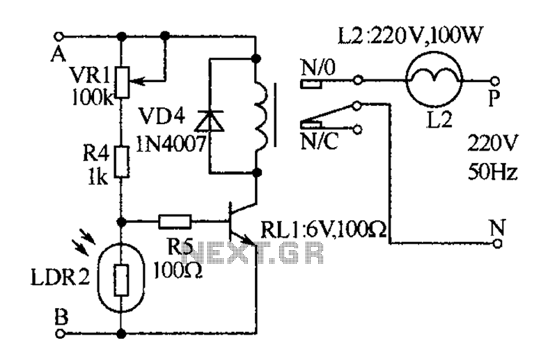
The receiver, as depicted in the figure, assists patients in avoiding missed audio signals during the daytime. The receiver operates independently, and the lighting will automatically turn off. At night, the lighting signal receiver activates simultaneously with the patient's...
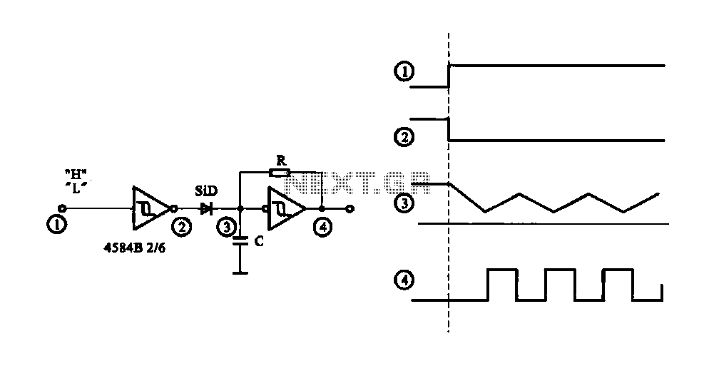
The circuit generates a controlled pulse signal. When a high pulse signal is applied to the input terminal O (start), the output pulse signal is activated. Conversely, when a low signal is received at the input terminal O (stop),...