
Amplified Noise Limiter For Sw Receivers Circuit

The noise limiter circuit is designed to reduce unwanted noise in audio signals while preserving the desired sound quality. The preamplifier serves as the initial stage, where weak audio signals in the range of 5 to 50 mV are amplified to several volts peak-to-peak. This amplification is crucial as it raises the signal level to a point where subsequent processing can effectively manage noise and distortion.
Following amplification, the signal is fed into a clipper circuit. The clippers are essential for limiting the amplitude of the audio signal, effectively preventing distortion that can occur when the signal exceeds a certain threshold. This process helps maintain audio fidelity by eliminating peaks that could introduce clipping artifacts.
The audio signal then passes through a voice band filter, which is specifically designed to allow frequencies within the human vocal range to pass while attenuating frequencies outside this range. This filtering is vital for applications such as communication systems, where clarity of speech is paramount.
Additionally, the circuit incorporates a narrow band active filter that can be switched in and out of the signal path. This feature allows for further refinement of the audio signal by selectively enhancing or suppressing specific frequency bands based on the requirements of the application. The ability to toggle this filter provides flexibility in adapting the circuit to various audio environments, ensuring optimal performance under different conditions.
Overall, the noise limiter circuit is an effective solution for managing audio signals, enhancing clarity, and reducing noise without compromising the integrity of the original sound. The noise limiter circuit has a preamplifier clipper, and a switchable audio bandpass filter. Audio levels in the 5- to 50-mV range are amplified in a preamp to several volts p-p, fed to a clipper, voice band filter, then to a narrow band active filter which can be switched in and out of the circuit.
Related Circuits
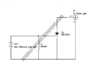
The following circuit illustrates a Slave Flash Light Control Circuit Diagram. Features include a 68mH inductor that provides an automatic trigger for the secondary flash light. The Slave Flash Light Control Circuit is designed to manage the operation of a...
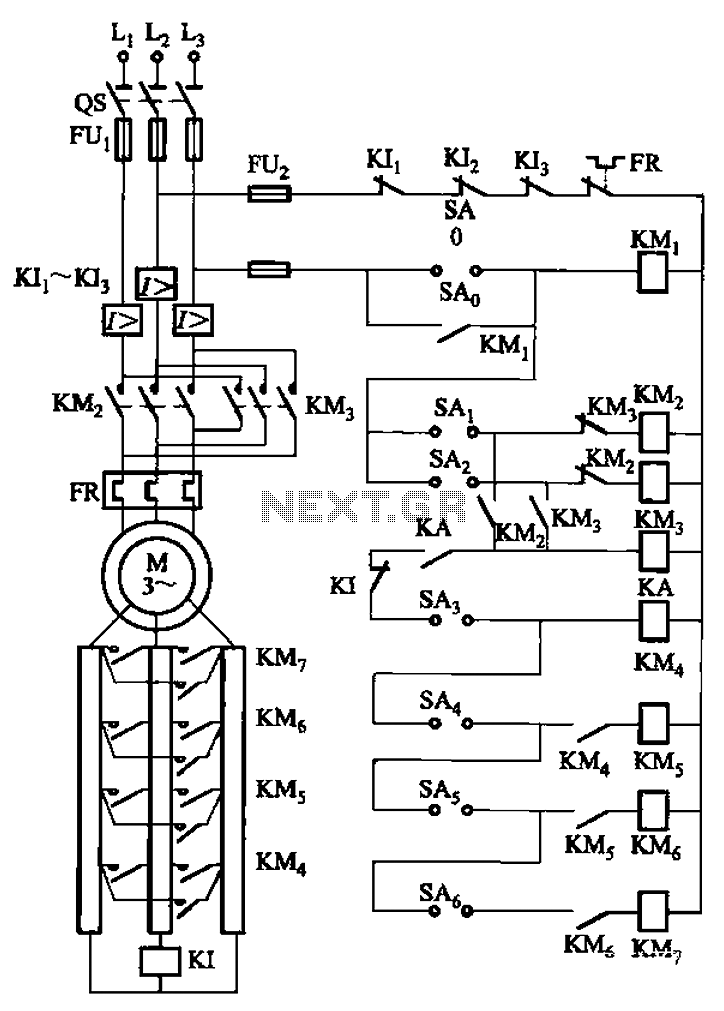
The circuit depicted in Figure 3-168 utilizes a controller for speed grading and reversing control. A reverse brake is connected to the rotor circuit through an overcurrent relay, labeled KI, for control. The current relay KIi to KI3 serves...
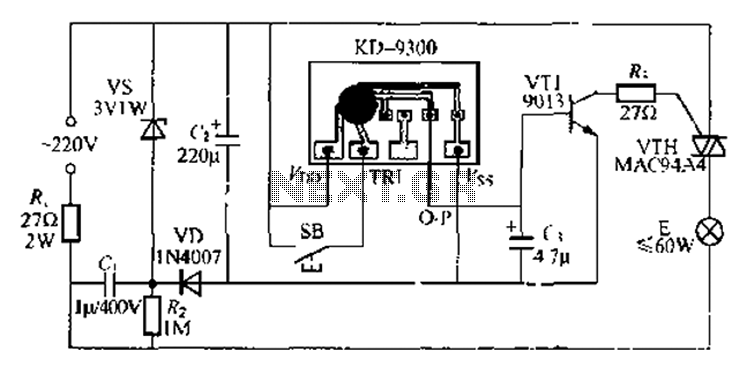
The circuit utilizes a KD-9300 music IC, which activates when the button switch (SB) is pressed, causing the electric lamp (E) to light up for approximately 20 seconds before automatically turning off. The setup includes a half-wave rectifier and...
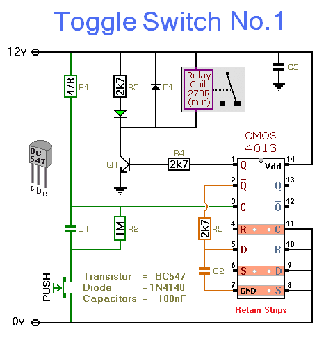
This simple circuit will energize and de-energize a relay with the push of a button. Pressing the button once will energize the relay, while pressing it a second time will de-energize the relay. The accompanying circuit provides a solid...
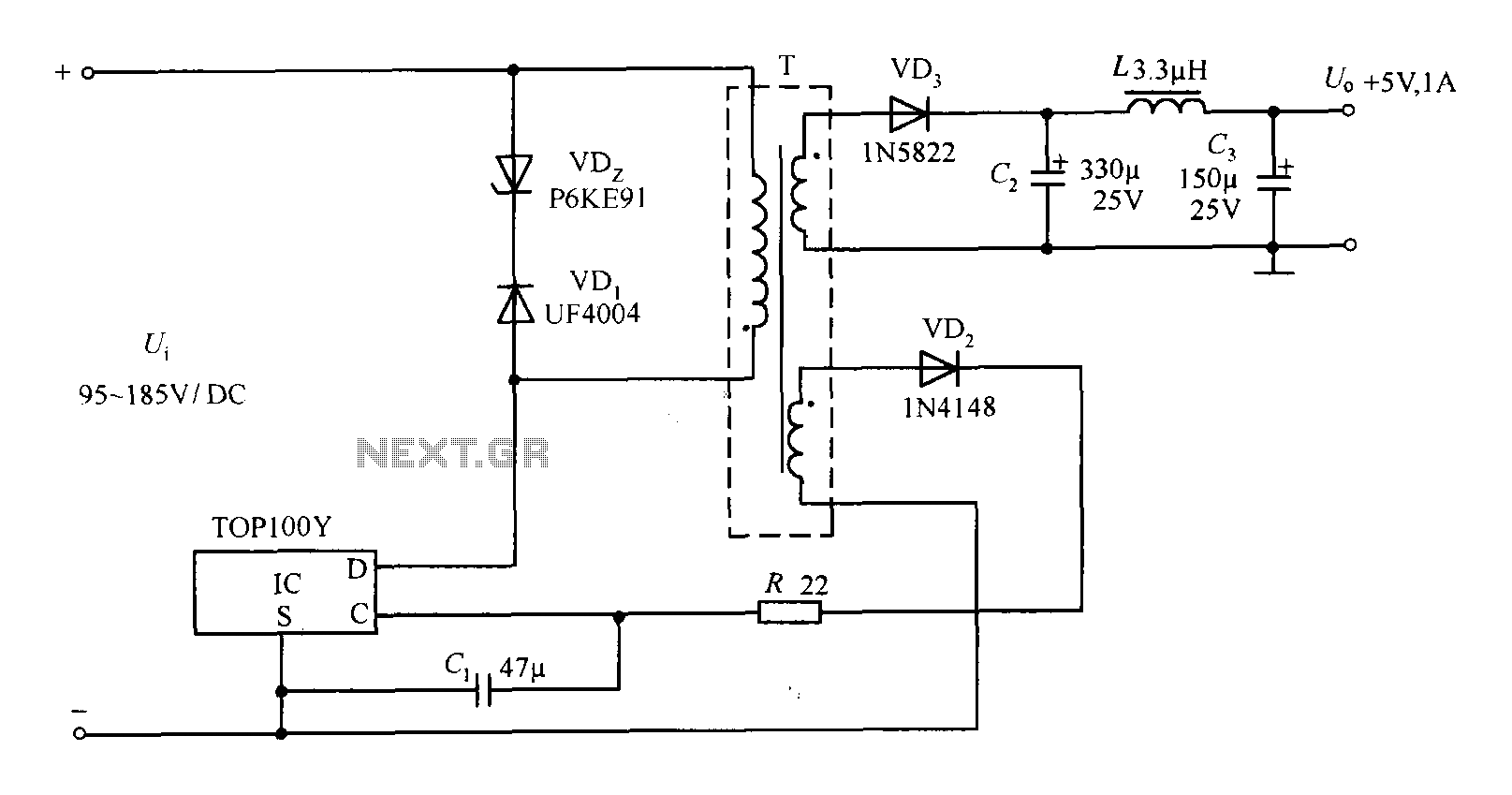
The TOP100Y is a flyback DC switching power supply circuit with a +5V, 1A output. This power supply features a feedback circuit that directly regulates the output voltage, making it suitable for applications that require electrical isolation and minimal...
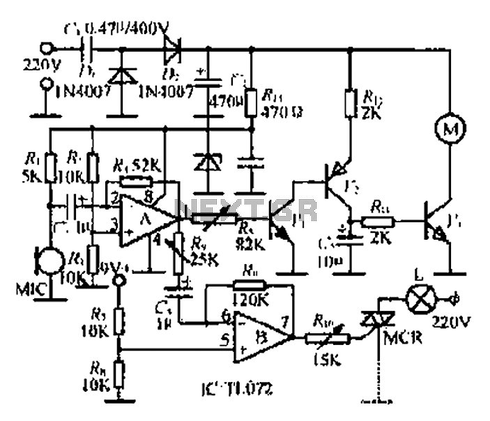
A microphone (MIC) is used to capture sound, which is then converted into a voltage signal. An operational amplifier (op-amp A) acts as a buffer; one output is directed to a motor drive circuit to control the motor's rotation...